GuideMiaGuideMia Technologies, LLC

GuideMia Implant Master

Quick Start Guide

An implant case from a folder of DICOM files to an exported surgical guide and a drilling report: a single unit, then a full arch, then the two set-up tasks that hold for every case. The whole guide on one page.

21950 words103 figures18 steps

Front matter

Intended use and safety

What the system is for, what its measurements are worth, contraindications, the risks of misplacement, the surgical precautions the guide itself is subject to, and where responsibility sits.

Read this before the workflow chapters. It is the part of the documentation that describes what the software is for, what it does not do, and where responsibility sits — none of which is obvious from using it.

What the system is for

GuideMia is a software interface that turns DICOM images from CT scanners into 3D models; an image segmentation system for creating dental anatomies from those images; and pre-operative software for simulating and evaluating dental implant placement and surgical treatment options. It includes a surgical guide design tool that transfers the treatment plan into geometric models wherever possible.

The stated purpose of that last part is worth reading twice, because it is the reason guided surgery exists:

This eliminates or reduces the risks that treatment plans are not correctly conveyed by the surgical guides.

The software runs on standard personal computer hardware under Windows.

What the measurements mean

The measurement features — dimensions and angles — are guaranteed to errors smaller than 0.01 mm or 0.05 degree.

That figure describes the software's arithmetic, not your case. Every deviation between a digital measurement and the physical anatomy depends on the accuracy of the data you put in:

Please refer to the specs of your CT and optical scanners for their accuracy information. GuideMia has no impact on the input data.

A plan is no more accurate than the scan it was built from.

Who may plan a case

Implant treatment planning should be performed only by practitioners or lab technicians who are trained to do so. Necessary training includes Implant Dentistry, CT Imaging Concepts, and GuideMia training courses.

The software does not substitute for any of that. It also expects the study work to have been done: adequate examination of the anatomic structures, and assessment of the biomechanical, functional and aesthetic requirements of each case. Radiographs or other diagnostic review should establish the position and topography of the maxillary sinus, nasal cavities, inferior alveolar nerve, mental foramen, natural tooth positions, and anything else bearing on placement or prognosis.

Consultation between surgeon, restorative dentist and dental laboratory is described as essential to success, not advisable.

Scanning, and what can go wrong before you start

The software can only be used when patients have been scanned according to specific protocols and procedures, with study models made and scanned where necessary.

Where a case uses a radiographic guide, its placement during the CT scan is itself a risk:

Improper placement of the radiographic guide during CT scan can cause serious errors and pose great risk to the surgery.

Contraindications

Implants should not be placed wherever there are general contraindications associated with elective oral surgery. The absolute and relative contraindications include, but are not limited to: cardiac and vascular disease, bleeding disorders, psychological disorders, uncontrolled diabetes mellitus, mineral, bone or connective tissue disorders, renal disease, hepatic disease, auto-immune disorders, decreased immune function through disease or medication, infectious disorders, and adverse conditions caused by medications. Further relative contraindications include poor oral hygiene, bruxism, malnutrition, alcoholism, tobacco use, and a history of radiation therapy.

Beyond the patient's general health, the site has to carry the plan: there must be adequate residual bone volume for implants of sufficient size and number to support the functional loads the patient will place on them. Narrow implants and angled abutments are not intended for use in the posterior region.

The risks of getting placement wrong

All implants must be placed with sufficient clearance between implants, teeth and nerve structures. The documented risks of improper placement and restoration include, but are not limited to: infection, implant failure, loss of bone and soft tissue, unfavourable aesthetic result, anaesthesia, dysaesthesia and paraesthesia in the oral and facial areas, sinus infection, dislodgement of implants and instruments into surrounding structures, damage to adjacent teeth, non-restorable implants, fracture of implants or restorative components, and loosening of implants or restorative components.

Implant systems measure differently

Each implant system has its own measuring characteristics for seating the implant to the intended depth, and they do not agree with one another:

In some instances, drill length reference lines measure longer than the stated length of the implant.

The surgeon is expected to be thoroughly familiar with the measurement system in use. This is the same concern that runs through placing the implant, where the surgical kit, sleeve diameter and drilling depth are set — and through the report, whose drilling instructions are what reaches the operating room.

Mixing systems

Each implant system also has its own design characteristics for mating implants, abutments, prosthetic components and instrumentation, surgical kits included.

Combining instruments, surgical kits, and components that are not configured or dimensioned for correct mating can lead to mechanical failure of components, damage to tissue, or unsatisfactory aesthetic results.

This is the clinical reason the software ties the guide to a named kit in placing the implant, and why customising a kit is a deliberate, documented operation rather than a convenience.

What guided surgery does not guarantee

One-hundred percent success cannot be guaranteed no matter a treatment is planned with software or physical models.

Inadequate quantity or quality of remaining bone, infection, inadequate surgical technique, poor oral hygiene and generalised disease are all potential causes of failed osseointegration — either immediately after surgery or after integration has initially been achieved. Pre-operative hard or soft tissue deficits may yield a compromised aesthetic result or unfavourable implant angulation.

For children, routine treatment is not recommended until completion of alveolar growth has been verified.

Procedural precautions for surgery

This section is about the physical object the software produces, and it is the part of the documentation most likely to be skipped and most costly to skip.

The guide is not a finished device.

The surgical guide model created by GuideMia is not intended for direct clinical use. The users must finish the surgical guide with additional drilling sleeves.

The software exports geometry. Sleeves are fitted afterwards, and the guide is not usable until they are.

Verify the guide before the surgery. The applicability of every guide must be verified beforehand, and quality assurance effort must be made to confirm it was made according to the designed model and to the treatment plan. That means trying it on diagnostic models, and on the patient's anatomy.

If a guide is found not fit properly on the patient's anatomy, or cannot be properly secured, it must not be used for the treatment.

Guides should also be visually inspected and evaluated, and any structure that could cause stress concentration identified and adjusted.

Minimise damage to the host tissue. Particular attention goes to thermal and surgical trauma, and to eliminating contaminants and sources of infection. The procedure requires a high degree of precision and care:

Any divergence from the principle of least possible trauma at implant installation increases the risk of failure to establish osseointegration.

Drilling. All drilling should be performed at a maximum of 1000-2000 RPM — or per the manufacturer's instructions — with copious irrigation. That holds with or without a guide designed by the system, and with or without a manufacturer's surgical kit. Essential to it are sharp drills, sufficient irrigation, an in-and-out drilling motion, short cutting cycles, waiting for the bone to cool, and pilot drills in successively increasing sizes.

This is the clinical basis for the irrigation windows described in step 10. A guide covers the site it drills through and a sleeve wraps the drill closely, which is exactly what obstructs the coolant this precaution requires.

An appropriate follow-up protocol should be followed.

Caution

The use of this device is restricted to, or by the order of, licensed physicians or dentists, and per the prescriptions of licensed physicians or dentists only.

Regulatory

The GuideMia Software System, model GuideMia-001, holds FDA 510(k) number K121466, approved 31 May 2012, and carries CE marking under notified body 1023.

Manufactured by GuideMia Technologies, LLC, Cypress, California, USA.

Where responsibility sits

The report each case produces carries a disclaimer and a signature line for the prescribing doctor, and it says this plainly: examination and diagnosis of the patient, and the determination and preparation of a medically sound treatment plan, are the prescribing doctor's alone.

The software plans. It does not diagnose, and it does not decide.
Front matter

Before you start

What a surgical guide is made of, the two families of guide, the five scanning protocols and how to prepare for each, what the software reads and writes, where it will struggle, and the terms it uses.

What this guide covers

This guide follows two complete implant cases from a folder of DICOM files through to an exported guide and a printed report, in the order the work actually happens.

Part One is a single unit: a posterior mandibular site, a CBCT with an intra-oral scan, a tooth-supported guide at the end of it. Thirteen steps.

Part Two is a full arch: a maxilla planned on a radiographic guide, four fixtures, three anchor pins, a tissue/tooth-borne guide. Five chapters, and they assume Part One rather than repeating it.
Part Three is two set-up tasks that are not case steps — expanding the implant library and customising the surgical kit — each done once and then true for everything you plan afterwards.

Where the software offers a choice neither case took, the step says so in a short "More on this page" section rather than walking it.

Not covered:

  • Bone reduction, sinus and bone grafting. All are pages in the workflow panel; neither recorded case uses them.
  • Clinical protocol. The guide says what each control does and what to look at. It does not tell you which implant suits which site, how much clearance to the canal is enough, or when to load. Those belong with your own protocol and your own training.

The shape of the work

Whatever route a case takes, implant planning in GuideMia has the same six stages behind it. Knowing them makes the step order obvious:

  1. Preparation. The patient's CT scan comes in, and anatomical structures — bone, teeth, nerve channels — are modelled from it. Optical scans of stone models or of the patient's dentition are imported and aligned with those structures. Steps 1 to 6.
  2. Viewing and diagnosis. Measurement and the archiving of diagnostic findings, alongside the planning tools rather than separate from them. Step 8 covers the views used for this.
  3. Planning. Implant selection, placement, adjustment and analysis. Steps 7 and 8.
  4. Simulation. There are always errors in the clinical outcome of an implant procedure, whatever the data source and whatever the planning technology. Simulation lets you evaluate a plan under extreme error conditions. Covered in accuracy.
  5. Design. Surgical guides, designed against your choice of surgical kit. Steps 9 and 10.
  6. Manufacturing. A lab makes the guide from the exported STL with no or trivial post-processing. Outside this guide.
What a surgical guide is

A surgical guide exists to improve the accuracy and safety of a treatment, so that implants are placed where they were planned, for the best achievable aesthetic and surgical outcome. Every guide has the same basic elements, and recognising them makes the design steps read as one thing rather than several:
  • An adaption surface, which fits onto the patient's anatomy. This is what steps 4 to 6 exist to produce and step 12 exists to verify.
  • Drilling holes with sleeves inserted, which embody the treatment plan and guide the actual drills. Step 7 determines these.
  • Optional form features — irrigation windows, screw holes, anchor pin holes, inspection openings. Step 10.

The two families of guide

Everything in the software follows from which surface the guide sits on, and there are only two answers.

Tissue-borne — also called tissue-level — guides sit directly on the patient's soft tissue and tooth surfaces, for non-invasive surgery. To make one fit, the system needs a duplicate or approximation of those surfaces, and it will take that from any of four sources:

  • A prefabricated denture-like guide, usually called a radiographic guide, whose digital model comes from a CT scan and surface reconstruction — the route Part Two follows
  • A stone or plaster model, scanned optically
  • The patient's intra-oral scan — the route Part One follows
  • An impression, digitised by CT or optical scan

Bone-borne — bone-level — guides are placed on the jaw bone, for invasive surgery in which the surgeon reflects the soft tissue. Here the geometric model of the bone and tooth structure is created from the CT scan itself, a model 2-3 mm thick is derived that fits the bone like a denture, and the drilling holes are cut into that.

Guides are designed to be used with a surgical kit. Implant manufacturers make kits to their own implant specifications, often with a version designed for image-guided surgery, and their job is to ensure the right drill sizes, orientations, depths and sequence. The guide has to be designed to match. When no kit exists for the implant a case uses, the guide is designed for pilot drills only — which is a real and useful outcome, not a failure, but it has to be a decision rather than a surprise.

The scanning protocols

The software can only be used on patients scanned according to specific protocols. Which one you used decides what the case can produce, and it is chosen in step 2 before any work is done. Beyond radiographic guides and dentures, GuideMia does not require or endorse scanning appliances, trays or help bodies of any kind.

ProtocolGuide levelCase typesMetal artefacts
CT + intra-oral scanTooth/gumPartially edentulous only, good tooth supportMust have none near the implant sites, or at least two complete tooth surfaces clear of scatter
CT + optical scan of stone modelTooth/gumPartially edentulous only, good tooth supportSame restriction
Dual scan with radiographic guide or dentureTooth/tissueFully or partially edentulousCrowns, implants and other artefacts may be present near the sites
Dual CT scan with stone modelTooth/gumPartially edentulous only, good tooth supportSame restriction as optical
Single CT scanBone/toothFully or partially edentulous; partial needs good tooth support, fully edentulous with very loose bone not recommendedMust have none near the implant sites

The pattern is worth stating plainly: metal artefact is what forces the dual scan with a radiographic guide. If a patient has crowns or existing implants near the site, the optical protocols will struggle, and the radiographic guide route exists for exactly that case.
What follows is the short version, enough to know whether the data you have will work. The full protocols — CBCT parameters, patient preparation and the radiographic-guide checklist — are on scanning protocols.

Preparing the patient for the CT scan

Common to every protocol:

  1. Remove all metal prosthesis and metal jewellery that might interfere with the region to be scanned.
  2. Secure the bite with cotton pads or another highly radio-translucent material such as polyethylene. Avoid any radio-opaque material, which will prevent the tooth surfaces from being segmented later.
  3. Upper and lower teeth must not touch during the scan.
  4. Leave 5-10 mm between the jaws (5-8 mm for the stone-model protocol).
  5. The patient must stay still, and must not move or swallow during acquisition.

Position so that the occlusal plane is parallel to the image slices, with no tilt, and set the height to centre the occlusal plane in the field of view. Where both arches are to be treated, provide a separate scan for each.

Slice thickness: 0.2-0.5 mm. Thinner slices demand more of the computer. Cases with slices thicker than 1 mm are not recommended at all — see accuracy.

Preparing the optical scan

  1. Scan the preparation area, preferably the full arch.
  2. Leave a 3-5 mm margin beyond the tooth surfaces.
  3. Where the case justifies a tooth setup and there are multiple units, place the teeth virtually in your scanner or CAD software and save the diagnostic model as a separate STL.
  4. For an immediate-extraction case, remove the tooth being extracted — not the root area — in the scanner or CAD software and save that as a separate STL. This and the previous step can be combined.
  5. Scan the antagonist. Recommended for both restorative and implant planning, and used in step 6.

Trim the scan along its edges if your scanner software can, keeping the margin above. Inspect the STL for overlapping triangles, self-intersections and holes before you bring it in — a defect that is invisible at registration will surface later, when the guide will not cut. 5-20 MB is a normal STL size for this work.

Preparing a radiographic guide

If your case takes the dual-scan route, the guide is where its accuracy is decided, and it is made before anyone opens the software:

  • Design it with prototype restorations, 2.5-4 mm thick, containing no metal or radio-opaque material, with buccal flanges extended enough for markers and anchor pins, fitting properly on the patient's anatomy.
  • Add 6-8 radiographic markers — gutta percha, radio-opaque glass beads or similar — 1.5-2.5 mm, spherical, never cylindrical or specially shaped. Half lingual, half buccal, and deliberately not evenly distributed.
  • Make a bite registration in radio-translucent material.
  • Scan twice: the patient wearing the guide, and the guide alone.

A denture can serve as the radiographic guide if it has teeth of proper size, shape and length, a well-established occlusion, buccal flanges wide enough for markers and pins, a hard reline only, a secure close fit, and no metal.

What the software reads and writes

FormatWhat it is
DICOM seriesCT scan datasets. GuideMia is DICOM-compliant and reads the series produced by the scanner
IMGA GuideMia format: a DICOM series combined into one file
STLImported optical scans and exported models — guides, master models, implants
XMLThe implant library
SGCSurgical kit configurations
HTML + PDFThe treatment plan report, with its image files

The three surfaces

Knowing which part of the interface owns what saves most of the hunting a first case involves:

The Wizard walks the steps. One page each, Previous and Next Step at the bottom, and only the controls that step needs.

The sidebars carry additional tools for the current page — the ones a straightforward case can ignore and a difficult one cannot.

The workflow pages, in the dock widget, hold the full interface, including advanced work the Wizard never surfaces. Each chapter of this guide ends with a More on this page section describing what lives there.

The Wizard is a path through the software, not a smaller version of it. Nothing it offers is unavailable elsewhere — but a good deal that lives elsewhere never appears in the Wizard.

Two things that will bite

Update after you change something. Several steps compute from inputs you set: change a parameter and the result does not follow until you tell it to. Add/Update Implant and Generate/Update surgical guide both work this way, and both will keep showing you the old geometry in the meantime.

Finish the registration. Alignment previews dynamically as you place markers, which looks finished long before it is. Pressing Align is what commits it.

Where the software will struggle

Some conditions the system either does not support or will not produce good results from. Recognising them before you start is cheaper than discovering them at guide design:

  • CT slice thickness over 1 mm — leads to inaccurate models.
  • Slices larger than 2048×2048 pixels — generally supported, but real-time performance depends on the hardware.
  • Too many slices. 512 slices is comfortable on the recommended configuration. More than 1024 is generally supported but slow — use Export DICOM file series to cut a smaller dataset from the volume of interest and plan on that.
  • Excessive scatter in the CT, from metal crowns, fillings or existing implants. This is the condition that pushes a case onto the radiographic guide protocol.
  • Very loose jaw bone where a bone-level guide is wanted, such that a bone model cannot reliably be built from the CT.
  • Poor-quality STL from the stone model or intra-oral scan — excessively tiny triangles, overlapping triangles and similar defects.

A note on versions

This guide was written against GuideMia Implant Master V8. The underlying workflow — and everything in this chapter — has been stable across releases, but the toolbar layout, the icons and the placement of individual controls differ between versions. Where you cannot find a button where a figure shows it, look for it by name on the workflow panel rather than assuming it is absent; the function is almost always still there.

The terms this guide uses

The software's vocabulary is specific, and several terms are used in ways that are not quite their everyday meaning.

Radiographic guide — a denture-like model carrying radiographic markers, fitting on the patient's teeth and/or soft tissue. Also called a scan template, and the software uses both names.

Segmentation — separating a particular structure out of a CT dataset.

Nerve tracking — following the nerve channels through the dataset and creating surface models of them, to simulate the nerves in the patient's anatomy.

Surgical guide — a model embodying the treatment plan, with implant holes and drilling sleeves, fitting the patient's anatomy, used to guide the drilling.

Master model — the patient's bone and tooth structure, optionally with soft tissue, with implant holes added. For case study, further planning, and guide fabrication.

Bone reduction guide — a guide with a base fitting the bone and an opening exposing the area to be removed.

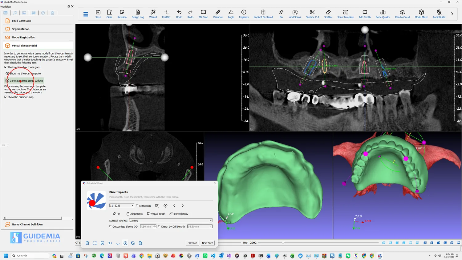
Virtual tissue model — a model generated from the CT to simulate the actual soft tissue and tooth surfaces. Named by analogy with a stone model, which includes the same surfaces.

Virtual tooth — a tooth model from an STL library, placed in the 3D views as a planning reference.

Safety zone — the space around an implant that must not interfere with adjacent roots, implants, nerves or sinuses.

Drilling sequence — the series of drilling operations making one implant hole. The first is the pilot drill.

Drilling sleeve — the metal tube inserted into the guide that guides the drill.

Assembly view — the 3D view showing the patient scan, the radiographic guide scan, the implants and every other model. Segment view, or current object view, is the other 3D view, showing only the current working object.

Arch curve — the curve outlining the shape of the arch, used to create the panoramic view.

Placement widget — the handles, axes and planes used to position a model in 3D.

Snapshot — a captured image of a rendering window together with the display parameters that produced it, so the same view can be recovered.

Part One — the single-unit case

A posterior mandibular site, planned on a CBCT with an intra-oral scan, finishing in a tooth-supported guide and a drilling report. Thirteen steps, in the order the work happens.

Part One · step 1 of 18

Creating the project

Load the DICOM series, set the volume of interest, and get a project on disk before any planning starts.

A case begins as a folder of DICOM files and becomes a project. This step is short, but two of its decisions shape everything after it: which file you point at, and whether you let the AI engine start work immediately.

Before a project is open

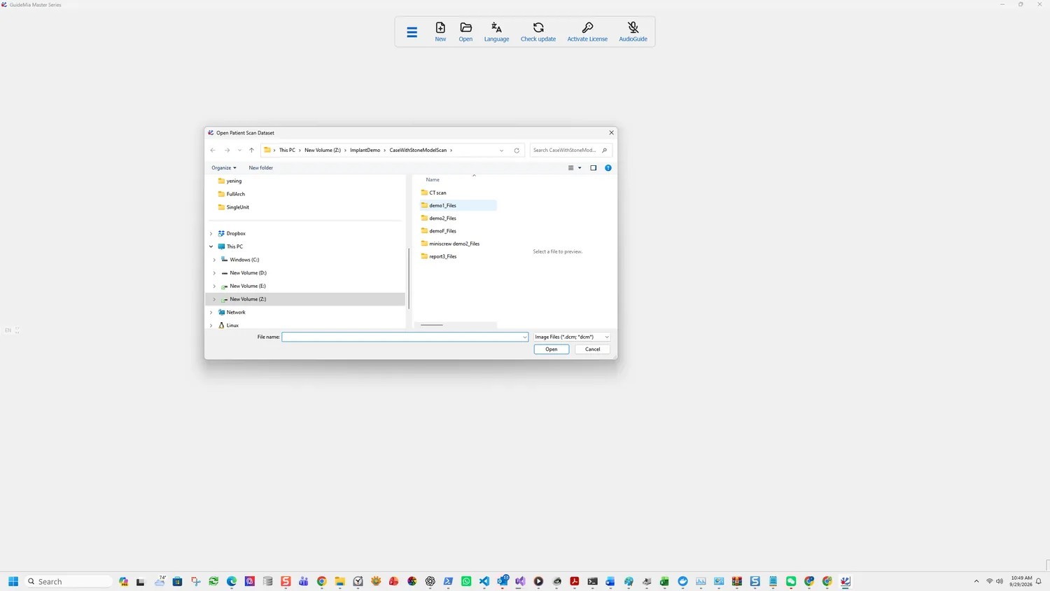
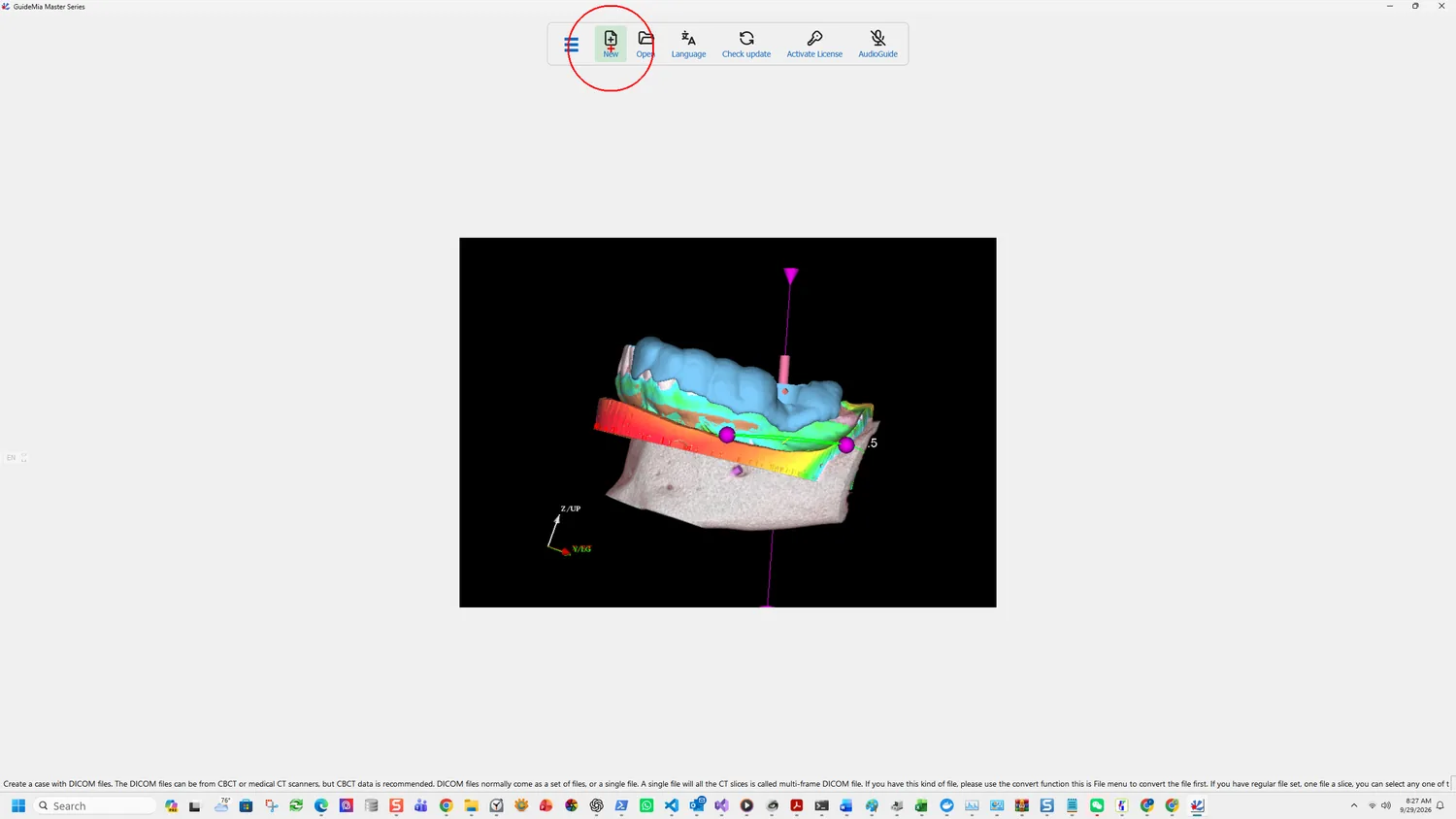
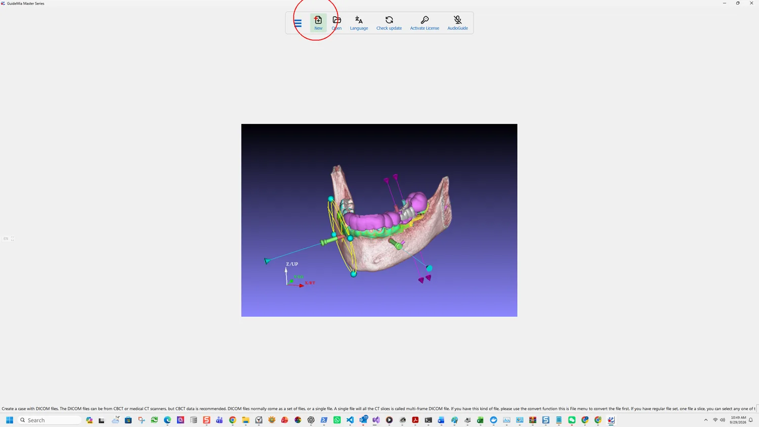
GuideMia starts with almost nothing on the toolbar — New, Open, Language, Check update, Activate License and AudioGuide. The planning tools only appear once a project exists.
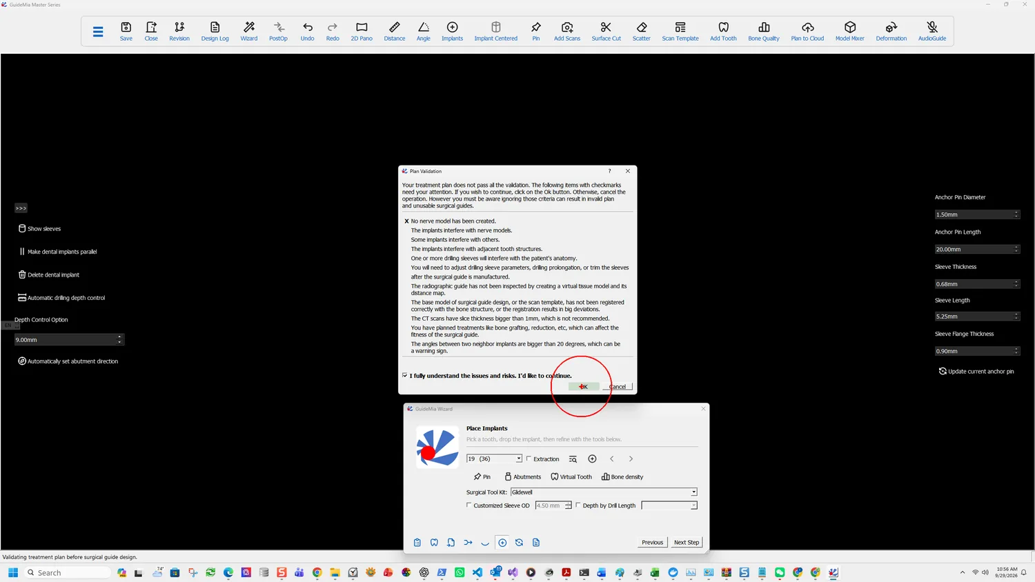
The startup toolbar, before any project is open

New creates a case from CT data. Open takes an existing project:

Open an existing project. It can be a project file or a package file, which can be saved using the function Save for Transfer.

Point at any one file of the set

The Open Patient Scan Dataset dialog

The instruction that saves the most time is this one:

If you have regular file set, one file a slice, you can select any one of the files. The system will open the entire dataset.

You do not select the folder, and you do not multi-select. One file is enough and the rest follow.

Three things about the data itself:

CBCT is preferred. The software accepts DICOM from CBCT or medical CT scanners, but CBCT is what it is designed around.

A multi-frame file needs converting first. A single file containing every slice is a multi-frame DICOM, and it has to go through the convert function in the File menu before it can be opened as a case.

Files without a .dcm extension are common. The dialog filters on Image Files (*.dcm; *dcm), so a set saved without extensions looks like an empty folder. Switch the filter to All Files and they appear — the files are fine, the filter is hiding them.
One patient's scan should be alone in its folder, with a single CT dataset in it.

Decide about AI segmentation straight away

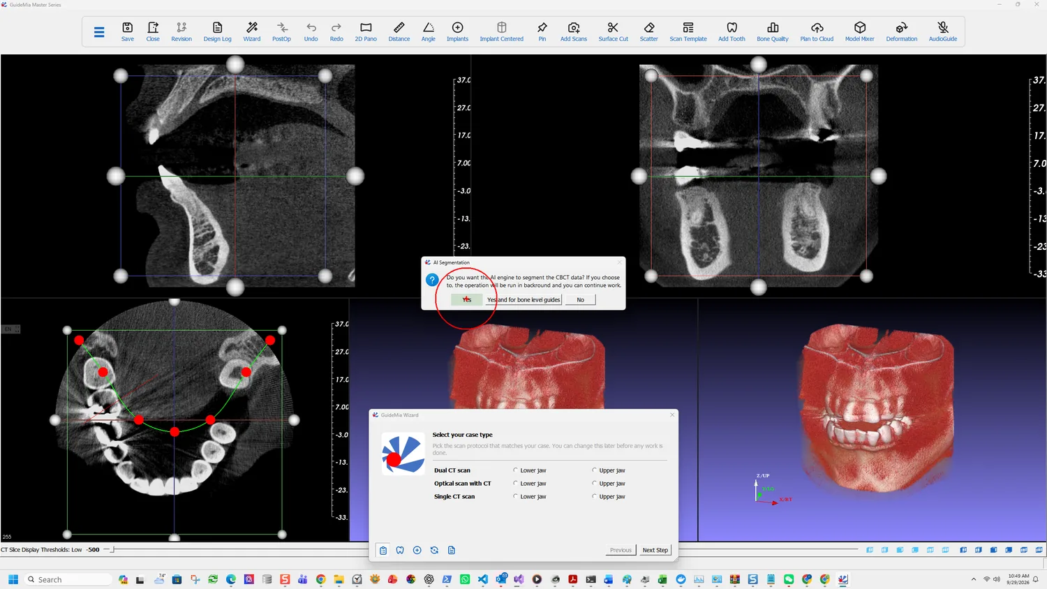
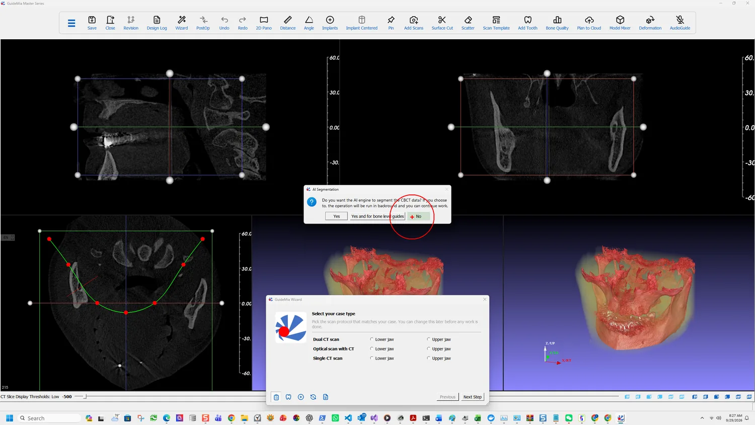
The AI Segmentation prompt, with the Wizard opening behind it

As soon as the volume loads, before you have chosen anything else:

Do you want the AI engine to segment the CBCT data? If you choose to, the operation will be run in backround [sic] and you can continue work.

Three answers, and they are not the same decision:

Yes segments the jaw — roots, bone and the nerve channels together. It runs in the background, so you can carry on while it works. Taking this makes the segmentation and nerve steps later in the Wizard into review rather than work.

Yes and for bone level guides does the same and prepares what a bone-level guide needs. Take it if the guide will seat on bone rather than on teeth; the extra work is done up front rather than discovered later.

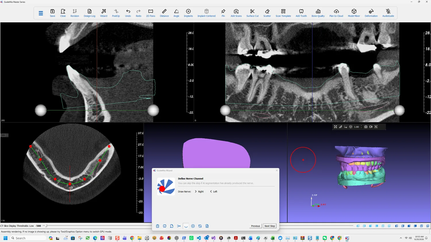
No leaves everything manual. The Wizard's segmentation step then matters in full, and the nerve has to be traced by hand.

The prompt appears once, at this moment. Choosing No here does not lock you out — the Wizard's segmentation page carries its own AI Segmentation button — but it does mean the background work never started, so you wait for it later instead of while you were setting the case up.

What the Wizard asks next

Behind the prompt, the Wizard has already opened on Select your case type, offering Dual CT scan, Optical scan with CT and Single CT scan, each for the lower or upper jaw. That choice is the next step.

More on this page

The full Load Case Data page in the workflow panel carries the routes this case does not take:

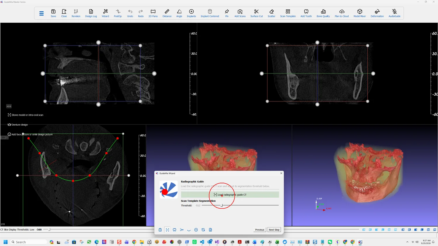
  • Radiographic Guide CT or optical — for fully edentulous cases, where the guide represents the gum surface and possible tooth arrangement; and for partially edentulous cases where there is not enough natural tooth left to register a CBCT against a model scan.
  • Denture design — loads a digital denture design, which can be registered against a radiographic guide or just the gingiva model. GuideMia can add abutment holes to it, or generate a prosthesis guide so the clinician can check occlusion and guide position before any drilling.
  • Impression CT or optical — loads an impression scan. The model builder extracts its inner surface and turns it into a solid dental model.

Also on that page: Save Revision stores a treatment plan — the implants and their positions — and Switch to selected plan brings a saved one back as the working plan. Useful when a case needs two options presented side by side.

Part One · step 2 of 18

Choosing the case type

Pick the scanning protocol and the jaw. This decides which guide family the case can produce, and it can only be changed before work begins.

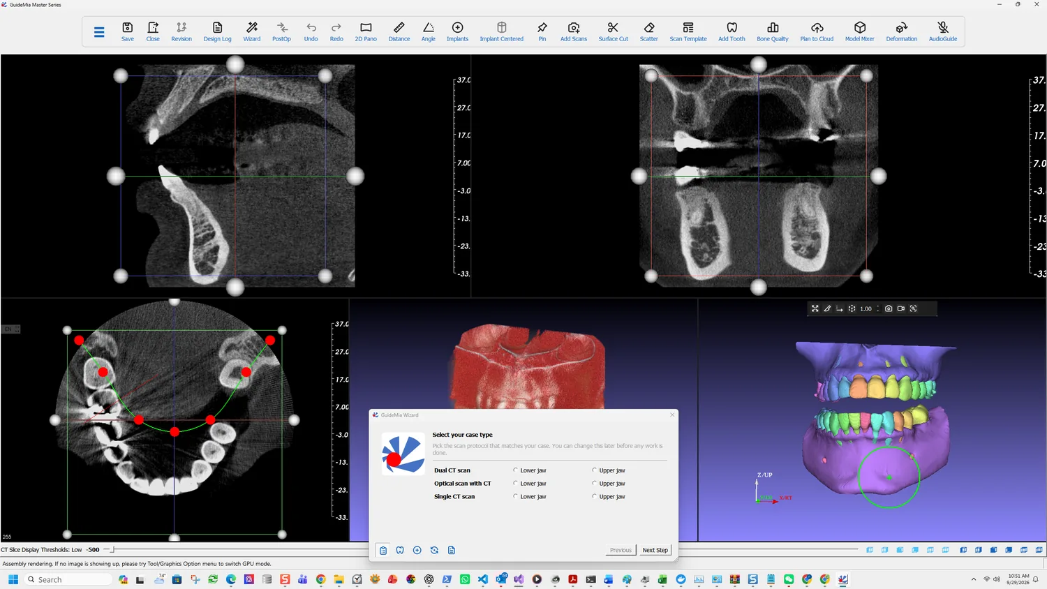
The Wizard opens on a question that decides which steps you will see for the rest of the case:

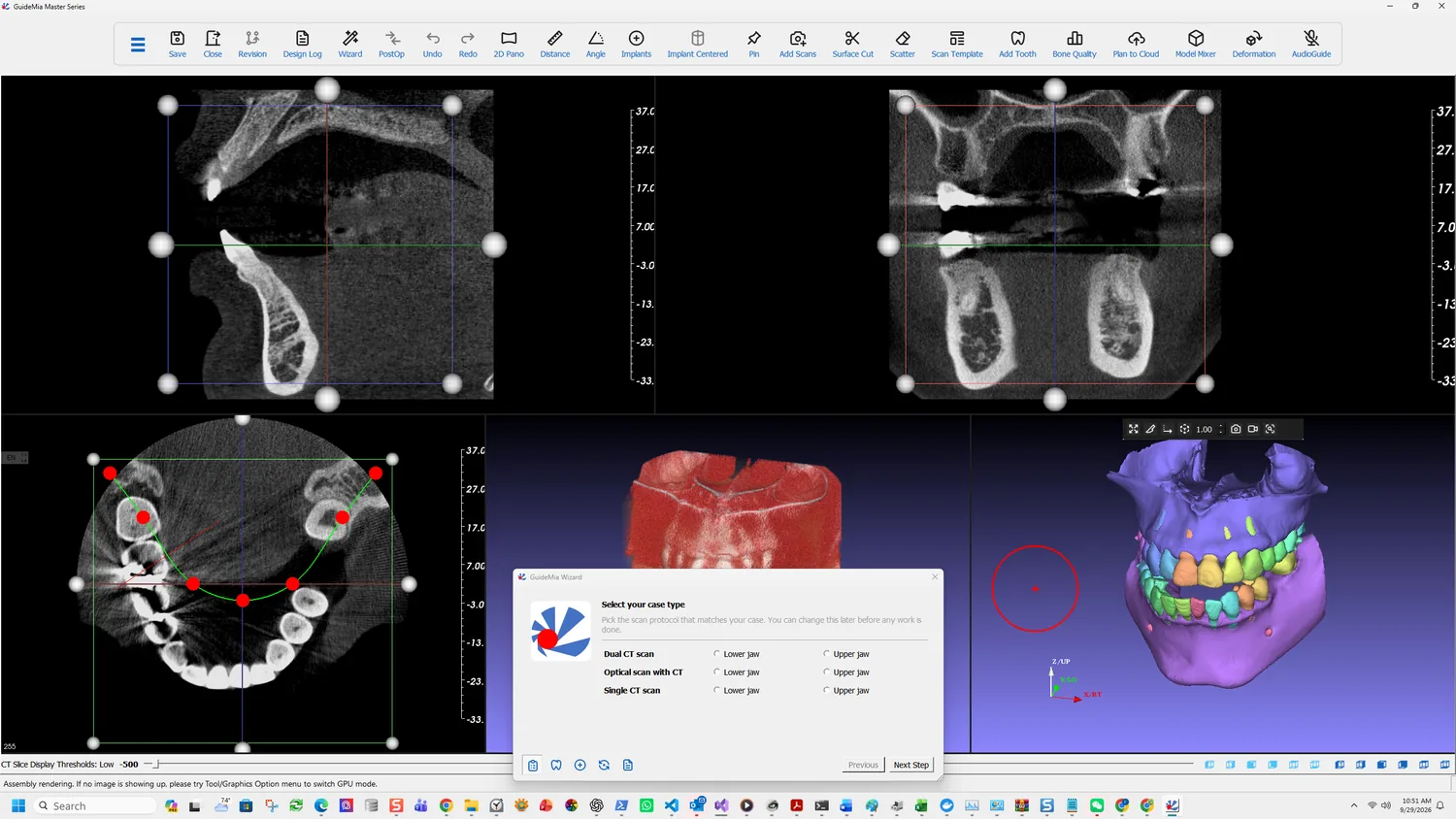
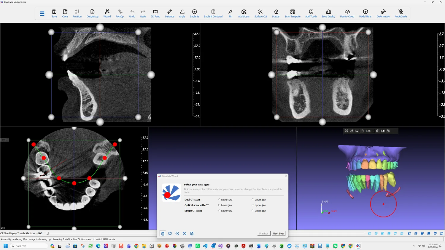
Select your case type, over a workspace where the AI has already segmented the arches

Select your case type. Pick the scan protocol that matches your case. You can change this later before any work is done.

Note the second sentence. It can be changed — but only before any work is done. This is not a preference you revise mid-case, because the steps that follow differ, and the work already done under one protocol does not carry across to another.

The three protocols

Each is offered for the lower or the upper jaw.

ProtocolWhat it takesWhat changes
Dual CT scanPatient CBCT plus a CBCT of a radiographic guideA registration step for the guide replaces the optical scan steps
Optical scan with CTCBCT plus an intraoral or model scanThe route Part One follows
Single CT scanCBCT aloneNo scan to load or register; the guide is built from the bone model

Optical scan with CT is the case recorded here, and the common one for a partially edentulous patient. The intraoral scan carries the tooth surfaces the guide will sit on, at a fidelity CBCT cannot reach.

Single CT scan is worth knowing about even if you never plan one, because it changes what the guide rests on. With no optical scan, the bone segment becomes the base for guide design, and the software builds a cylindrical clearance between the guide and the bone and tooth model so the guide sits on the neighbouring teeth rather than intruding into soft tissue or bone. No tissue information is needed and no flap is required. The release notes describe the sequence: load the CT, segment bone — preferably with tissue peeling so the bone surface is not too rough — place implants, then on entering guide design answer yes when asked whether to design a purely tooth-level guide.

Dual CT scan is the older protocol, and it still has a place — it is the one Part Two takes. A radiographic guide represents the gum surface and the planned tooth arrangement for a fully edentulous case, and it also solves a partially edentulous case where there is not enough natural tooth left to register a CBCT against a model scan — a patient with a long bridge, for instance.

Choosing the jaw

The lower and upper options are not merely a label. They set which arch the region of interest, the segmentation and the nerve work apply to. A lower-jaw case gets the mandibular canal as a first-class object; an upper-jaw case is concerned with the sinus instead.

What is behind the dialog

The workspace is already populated, because the CT loaded before the Wizard appeared.

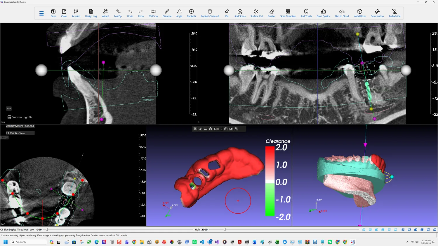
Three CT slice views — sagittal at top left, coronal at top right, axial at bottom left. Each carries a millimetre scale, a bounding box with handles that defines the region of interest, and slice lines you drag to move through the volume. The axial view also shows the arch curve with its control points; that curve is what the panoramic reconstruction follows.

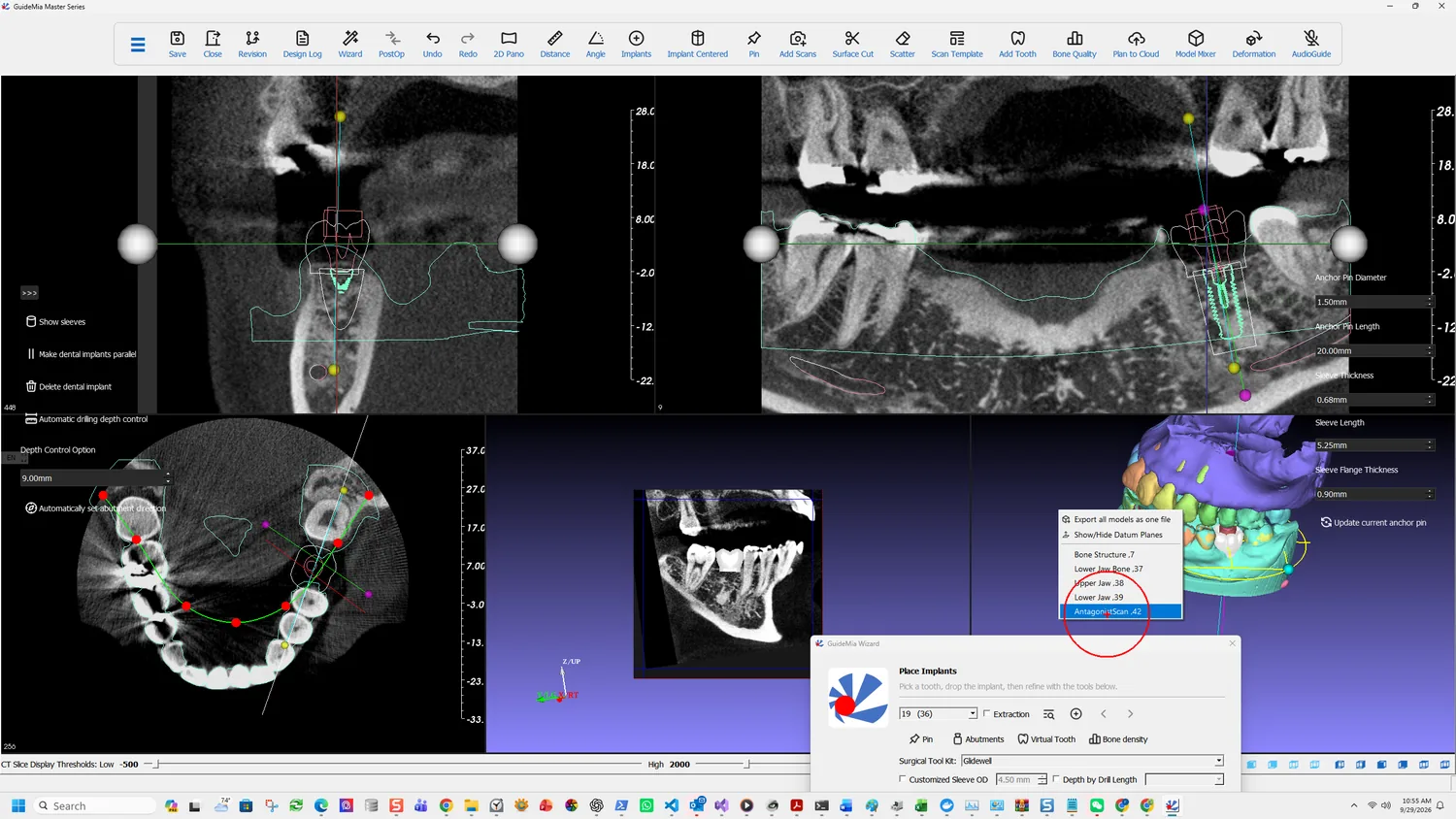
Two 3D views. The left is the working object window, the right the assembly window. The distinction matters later: in the assembly window you can right click any object and make it current, and it is then shown in the working object window. Export acts on the current object.

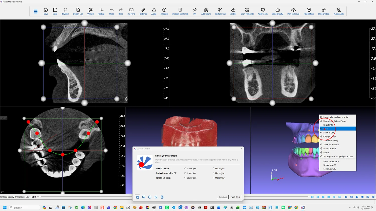
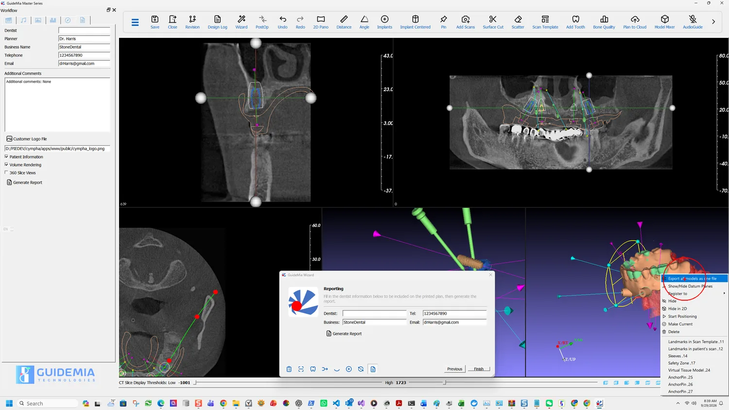
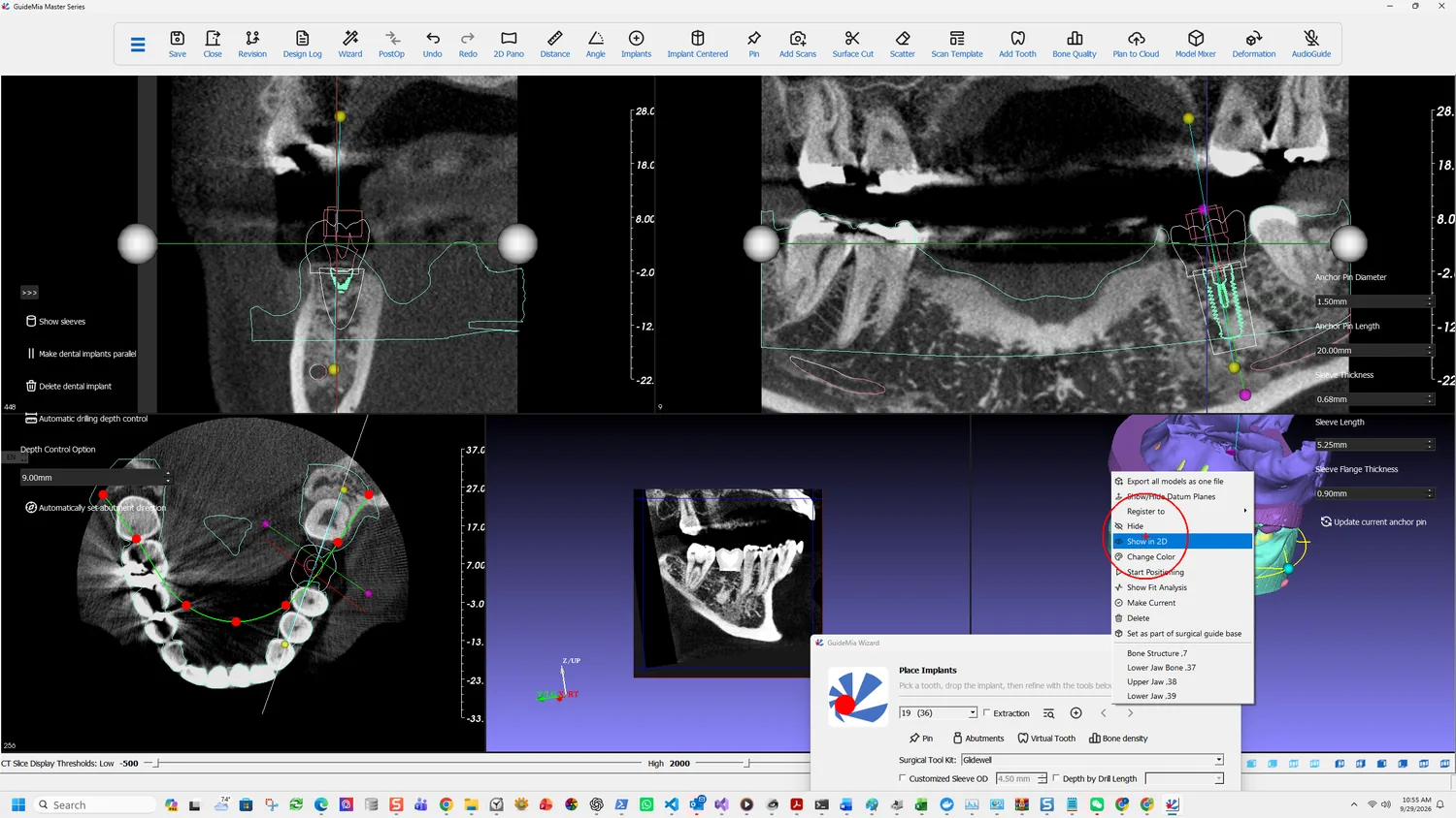
Right-clicking an object in the assembly window

That right-click menu is worth opening once now, because it is the same on every object for the rest of the case: Export all models as one file, Show/Hide Datum Planes, Register to, Hide, Show in 2D, Change Color, Start Positioning, Show Fit Analysis, Make Current, Delete and Set as part of surgical guide base.

Below the menu entries is the object list itself, and in this case it already reads Bone Structure, Upper Jaw and Lower Jaw — the AI has segmented the volume before you have chosen anything. That is why the 3D view behind the dialog is already showing separated, coloured teeth.

The threshold control along the bottom reads CT Slice Display Thresholds with a Low value. This is a display control — it governs what the slice views show. The thresholds that build the bone model are a different thing, set during segmentation.

How the interface divides the work

Three surfaces, and knowing which owns what saves most of the hunting a first case involves.

The Wizard walks the steps. One page each, Previous and Next Step at the bottom, and only the controls that step needs.

The sidebars hold the extra tools for the current page — the ones a straightforward case can ignore.

The workflow pages, in the dock widget, carry the full interface. They are grouped as Case Preparation, Treatment Planning, Surgical Guide Design and Report Generation, and they contain work the Wizard never surfaces at all.

The Wizard is a route through the software, not a reduced version of it. Everything it offers exists on the workflow pages too, which is why a case that needs something unusual is not stuck — you leave the Wizard for that step and come back.

More on this page

The Workflows button turns the Wizard on and off. V6 added a workflow customisation tool, so the sequence of pages is itself configurable rather than fixed — useful for a practice that always runs the same protocol and wants the irrelevant steps gone.

Part One · step 3 of 18

Segmenting the bone

Build the bone, tooth, root and nerve models from the volume — with AI, or with thresholds and seed points where the scan makes that hard.

Everything downstream is measured against the bone model. The nerve is drawn relative to it, the implant is judged against it, and in a CT-only case it becomes the surface the guide sits on. This step decides how faithful all of that is.

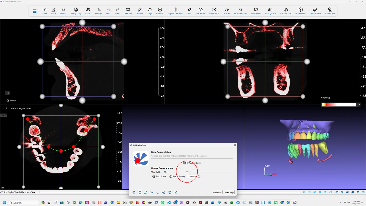
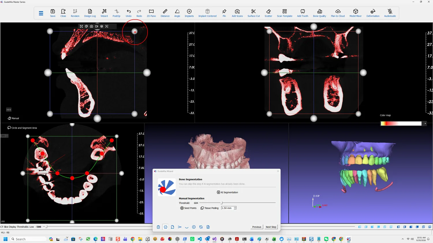
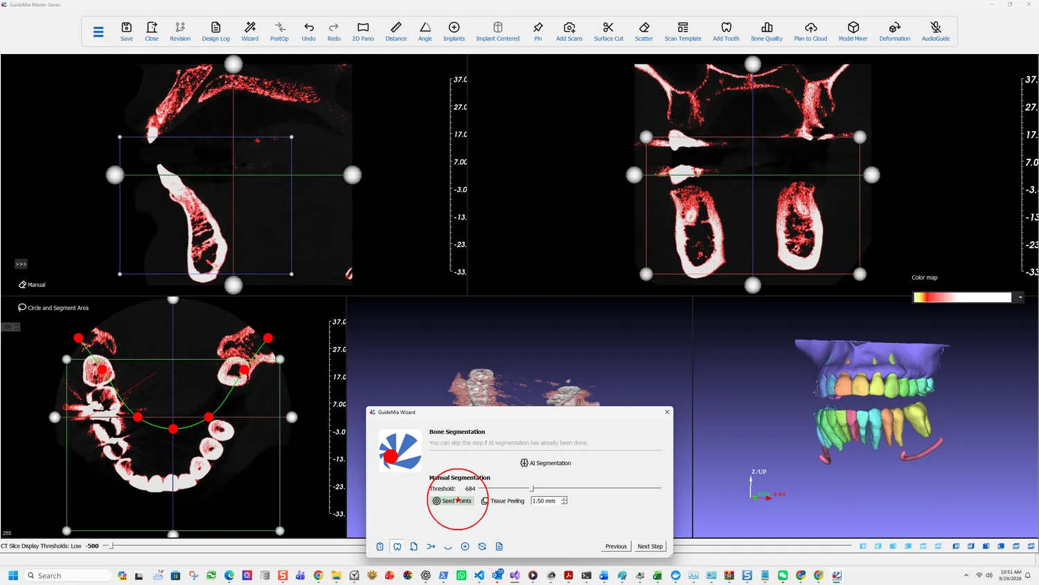
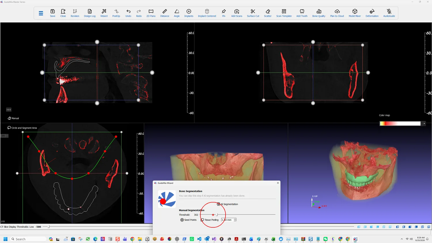
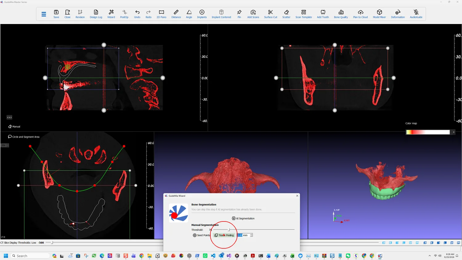
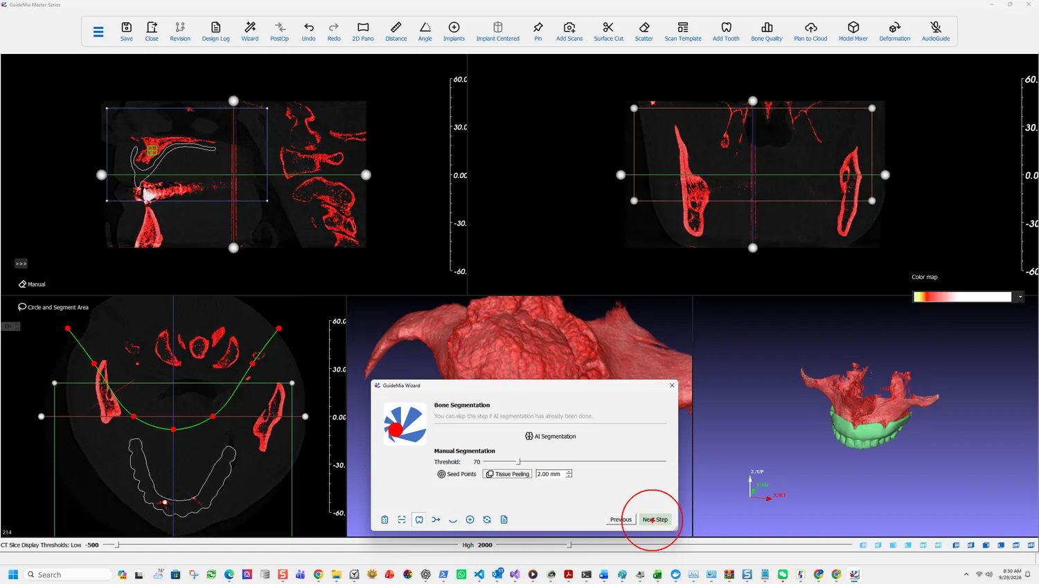
The Bone Segmentation page, with the thresholded voxels shown in red across the slice views

If you said yes at the start

The AI engine was offered the whole jaw when the project opened. If you accepted, this step is review — the Wizard says so:

You can skip this step if AI segmentation has already been done.

The Bone Segmentation page — AI Segmentation above, the manual controls below

AI segmentation produces roots, bone and the nerve channels together, which is why both this page and the nerve page become checks rather than work. The 3D view arrives with every tooth already separated and coloured.

What the AI produced: bone and separated teeth, both arches

What there is to check is whether the separation is right where it matters — at your implant site and its neighbours. Hide the bone structure and the roots come into view underneath it:

The same case with the bone hidden, showing the segmented roots

Roots are the reason this matters beyond appearances. The clearance between a planned fixture and an adjacent root is judged against these models in step 7, so a root the AI merged with its neighbour is a check you will not get.

It runs in two stages, and they behave differently:

The segmentation has two stages. The first stage is CBCT segmentation. While it is running you can continue your design. The second stage is actually to create 3D geometries. At that time, you would need to wait till it is finished.

So the first half costs you nothing; the second is a wait. If you declined at the opening prompt, the AI Segmentation button on this page starts the same work — you have simply lost the head start.

Doing it by hand

Manual segmentation takes three inputs, in this order. The order matters: seed points placed before the thresholds are right will select the wrong thing.

Thresholds

The values are Hounsfield units, as in the CBCT data itself. Properly calibrated data runs from −1024 to under 10000, though some scanners produce a wider range.

As you move the threshold, two things update at once: the filtered area in the 2D slice windows, shown in red, and the 3D rendering. You are not working blind, and you are not aiming at a number — move it until the selection represents the patient's hard tissue.

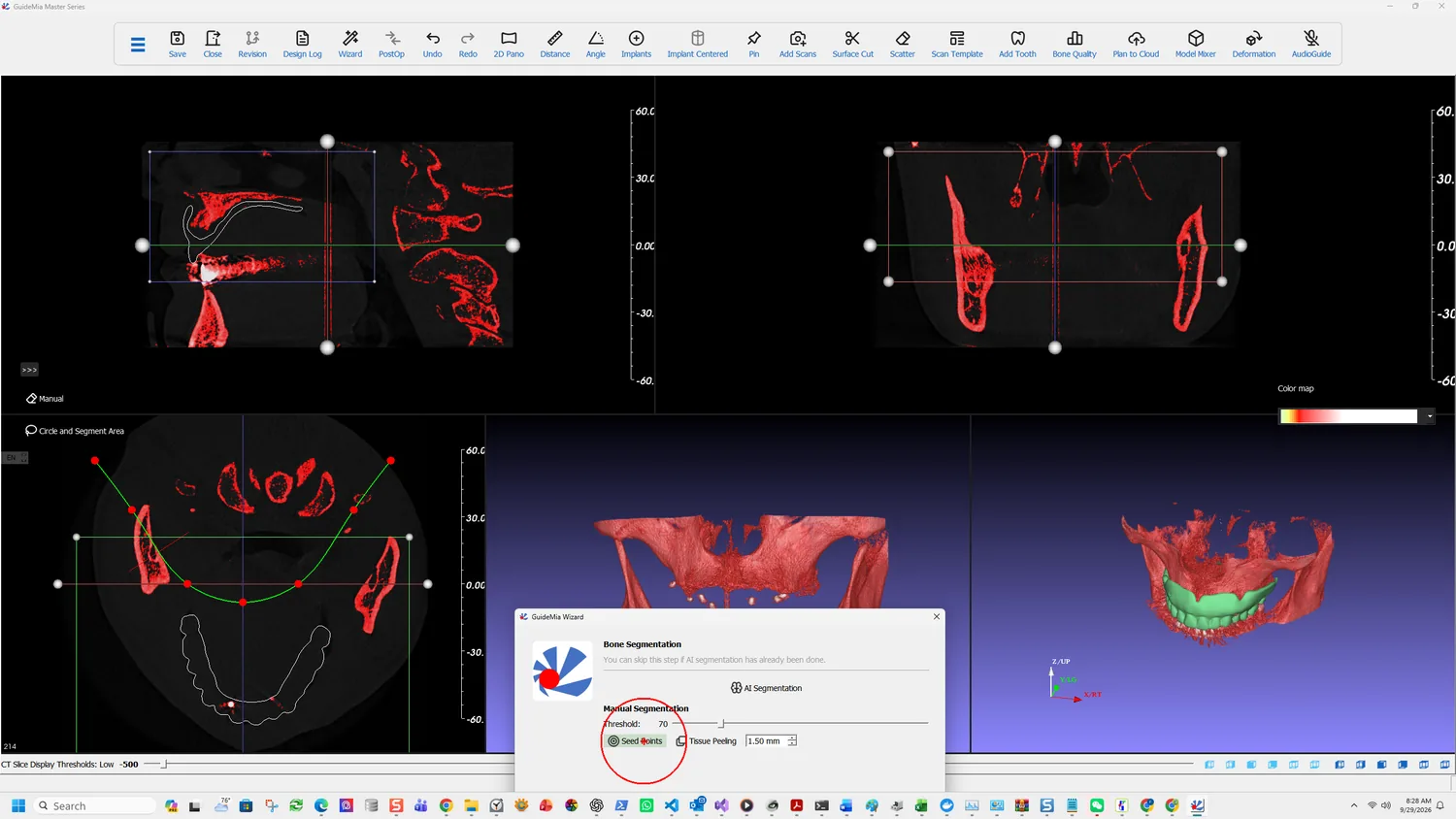
Seed points being placed on a slice

Region of interest

Each 2D window carries a box with handles. Resize them so the box contains the jaw you are working on and no more. Everything outside it is excluded from the segmentation, which is the cheapest way to drop the opposing arch, the cervical spine and the scanner's own artefacts.

Seed points

Thresholding alone leaves disconnected components and areas you do not want. A seed point picks the part you mean, and one is usually enough:

Scroll through your 2D slices, and click a point on any of the views. In a typical scenario, for example, you are going to work with lower jaw, you can just pick a point in the lower incisor area. Do not pick the black area because the pixels there will be discarded after the thresholding.

That last sentence is the one that catches people. A seed dropped where the threshold has already excluded the voxels selects nothing, and the result looks like the tool is broken.

Use more than one seed only when you genuinely want separate areas.

Tissue peeling

The Wizard's segmentation page carries a Tissue Peeling control with a size in millimetres — 1.50 mm in this case. It is not a cosmetic smoothing pass:

This tissue peeling operation is used to fill in the holes on the bone surfaces and generate smoother bone model. Sometimes patients' bone dentistry is low, it is almost impossible to create a good solid model of the bone structure for 3D printing or bone level surgical guide design.

The parameter is roughly the size of the holes to fill — normally 1 to 3 mm or slightly larger. Reach for it when the bone is porous enough that the segmented surface comes out full of gaps, which is exactly the case where a bone-level guide would otherwise be impossible.

The same tool, other tissues

This is not only a bone tool. Lower the thresholds and the same three inputs segment soft tissue, or an empty space such as the sinus. The tool selects whatever the threshold admits; bone is simply the usual answer.

More on this page

The full Segmentation page in the workflow panel splits into three tabs — Bone, Template and Teeth — where the Wizard shows only the bone work. It also carries:

  • Circle and Segment Area, which segments a circled area of the current bone structure into its own surface model. That model can be exported, or combined with further segmentations to build a bone-level surgical guide.
  • The Virtual Tissue Model page, for cases where the soft tissue has to be represented rather than inferred.

A note on what you are looking at while you work: the two 3D windows have different jobs. The right-hand assembly window shows everything; right-click an object there to make it current, and it appears alone in the left-hand working object window. Hide removes an object from view without deleting it, which is how you get the bone out of the way to look at the teeth beneath it.

Part One · step 4 of 18

Loading the optical scan

Bring in the intra-oral or model scan that will make the guide fit teeth rather than approximate bone, and look at it before you register it.

The CBCT knows where the bone and the nerve are. It does not know what the tooth surfaces look like — not at the fidelity a guide has to seat on. That is what the optical scan is for, and loading it is a step of its own before the two are brought into the same coordinate system.

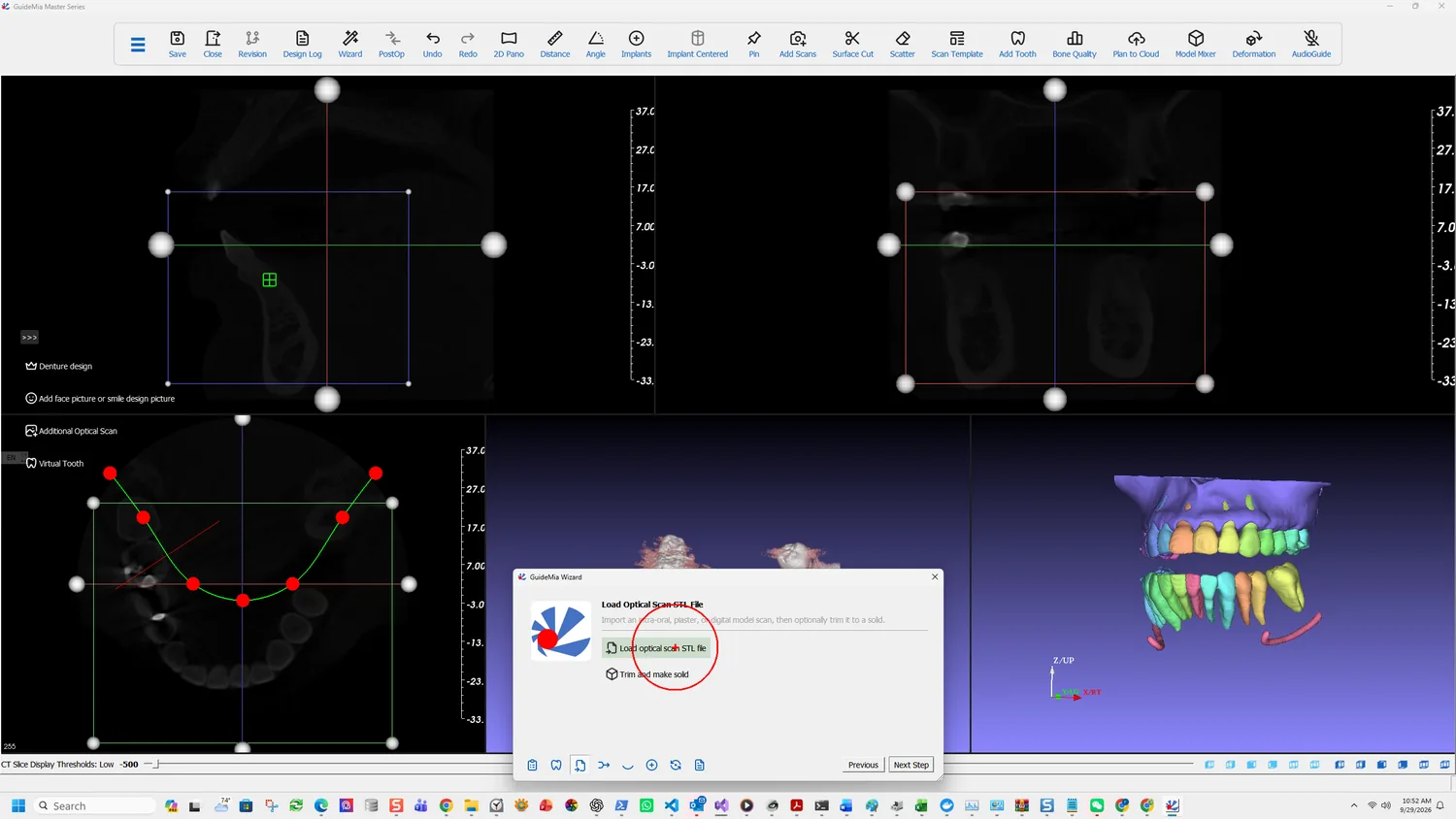
Load optical scan STL file

What counts as an optical scan

The software is deliberately unfussy about where the surface data came from:

Load optical scan of the teeth and gingiva. You can use a plaster model scan, an intra-oral scan, or even a digital model designed from another system. This is for partially edentulous cases so that surgical guides will be generated using the scan file.

Three routes, then: an intraoral scan, a scan of a plaster model, or a digital model built elsewhere. All arrive as a mesh file and all serve the same purpose.

The last sentence states the indication plainly. This is the partially edentulous route — the guide will be generated from the scan, seating on teeth that exist. A fully edentulous case has no such surfaces and goes the radiographic guide route instead.

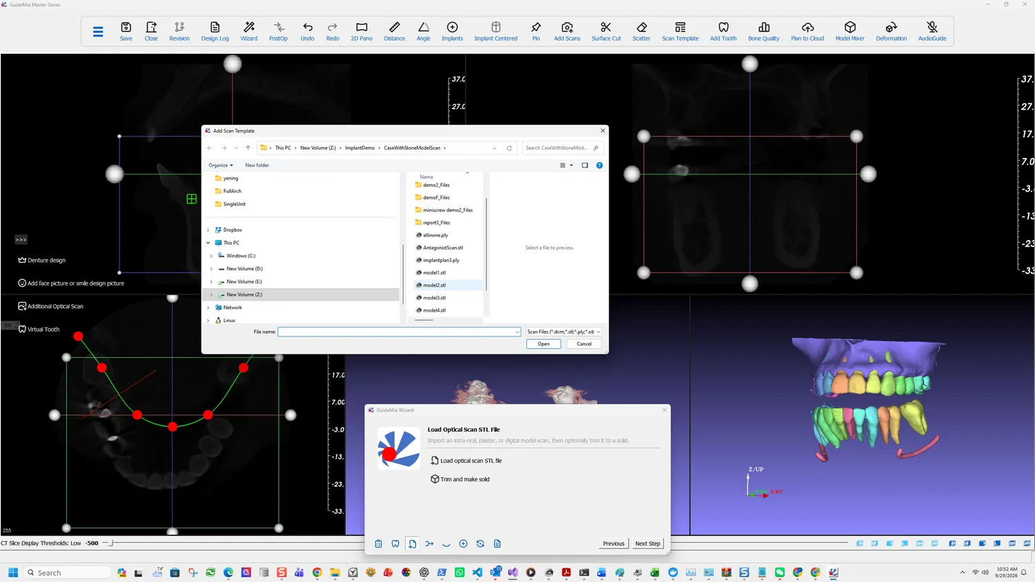
Selecting the scan file

Add Scan Template opens an ordinary file dialog. The scan loads as its own object, in its own coordinates, and sits alongside the CT-derived models without any relationship to them yet.

The scan loaded, before registration

What you are looking at

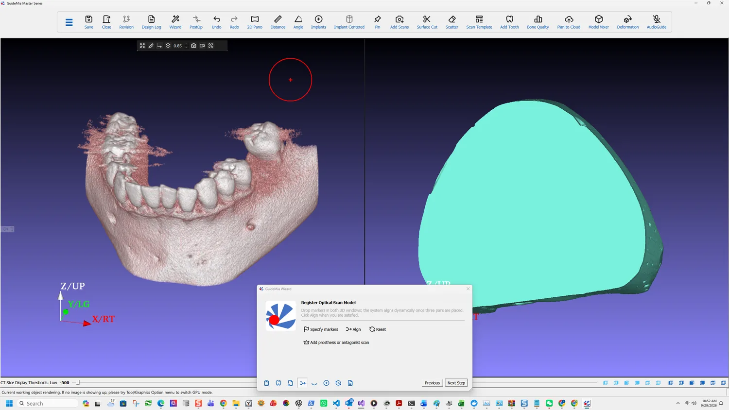
After loading you have two models of the same arch that disagree about where they are in space. The CT-derived bone and teeth carry the scanner's coordinates; the optical scan carries its own. Neither is wrong, and nothing can be planned across both until they agree — which is the next step.

It is worth rotating both before registering. A scan with obvious defects — holes in the occlusal surfaces, a torn margin, a swallowed area of palate — is better fixed or re-taken now than discovered when the guide fails to cut. The software can repair a scan later, but the failure surfaces at guide design, several steps after the cause.

The scan seen from its base

Turn it over first. The underside tells you whether the scan was trimmed cleanly and whether it is closed; a scan that is open where the guide will seat is the one that defeats Cut later.

The same scan, occlusal view

Then look at the occlusal surfaces, which are what the markers in the next step will be placed on and what the guide will rest on. You want unambiguous cusps and grooves. If the scan is soft there — smoothed over, or holed — the registration will be harder to place well and the fit will be harder to verify.

More on this page

The full Load Case Data page carries the alternatives this case does not use:

  • Radiographic Guide CT or optical — loads a radiographic guide's CBCT or optical scan. Two indications: a fully edentulous case, where the guide represents the gum surface and possible tooth arrangement; and a partially edentulous case where there is not enough natural tooth to register CBCT against a model scan, such as a patient with a long bridge.
  • Impression CT or optical — loads an impression scan rather than a model scan. The model builder extracts the inner surface of the impression and turns it into a solid dental model, so an impression can substitute for a poured model.
  • Denture design — loads a digital denture design, which can be registered against a radiographic guide or the gingiva model alone. GuideMia can then add abutment holes to it, or generate a prosthesis guide so the clinician can check occlusion and guide position before any drilling happens.

The Add Scans button on the main toolbar reaches the same loading functions without going through the Wizard.

Part One · step 5 of 18

Registering the scan

Pair matching points across the scan and the volume, align, and commit — the step whose accuracy every later one inherits.

Two models of the same arch, in two coordinate systems. This step makes them one, and the accuracy of everything afterwards rests on it: the implant is planned against CT anatomy and the guide is built on scan surfaces, so a registration error puts the drill somewhere the plan never intended.

Specifying markers across both 3D windows

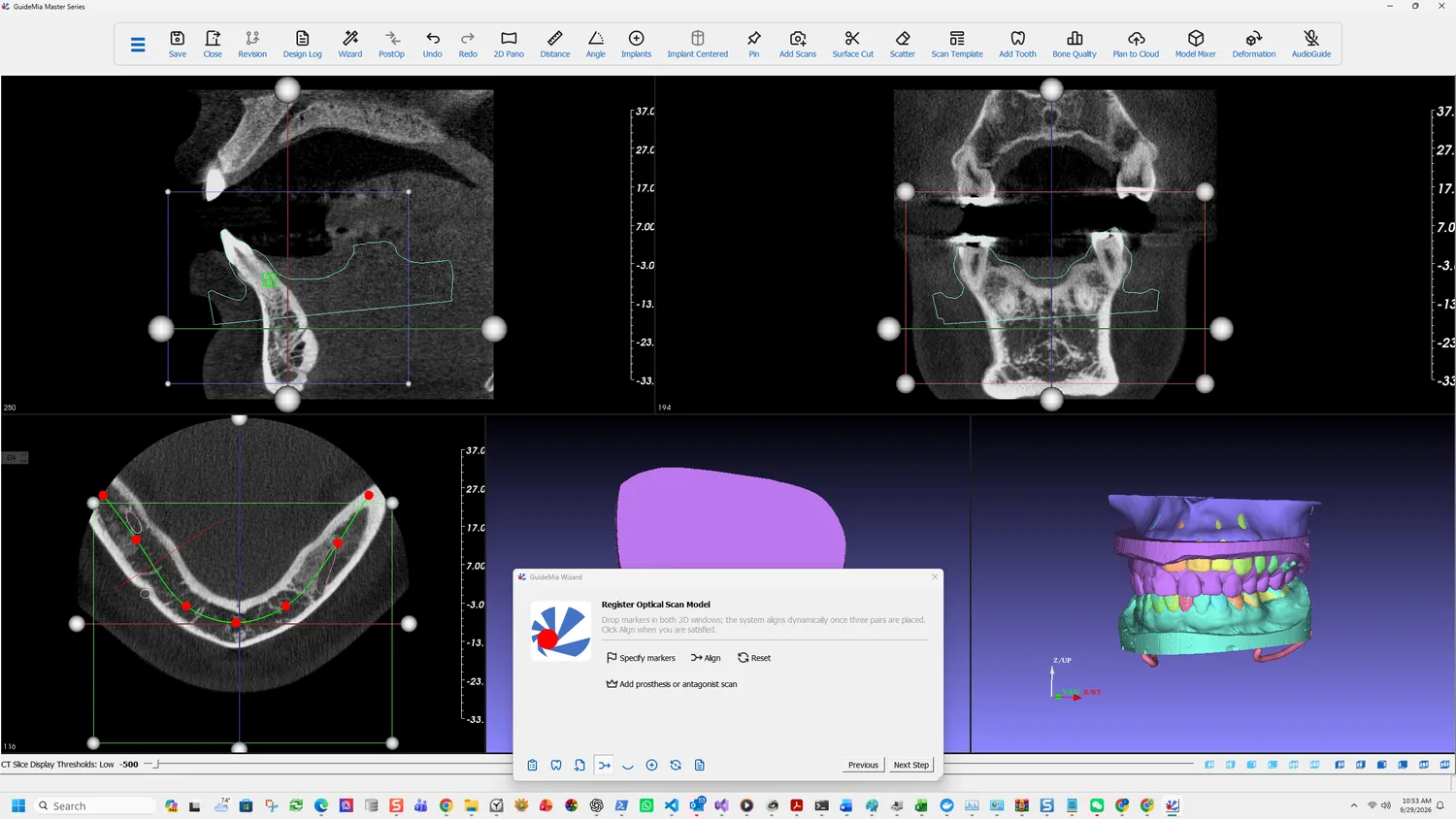
The Wizard states the method in a sentence: "Drop markers in both 3D windows; the system aligns dynamically once three pairs are placed. Click Align when you are satisfied."

Placing markers

Specify markers starts it. You are working across two windows — the CT-derived model on one side, the optical scan on the other — and clicking the same anatomical point on each.

Use this button to specify markers in the both 3D windows. The registration tool works dynamically. Once it has three pairs of points, it will start dynamic registration. You can observe the results and add more points on both sides. It is not required to specify markers in same order in the windows.

Two things in that are worth pulling out.

Order does not matter. You are not building a numbered correspondence; the tool works out which point pairs with which. So you can place three on one model and then three on the other, or alternate, whichever is easier to keep track of.

Three pairs starts it. Below three there is nothing to solve. At three the alignment begins computing and updating as you watch.

And one caution that reverses the obvious instinct:

More markers may not produce better results.

More points do not average out to a better fit. A badly placed marker is weighted like a good one, so adding points to compensate for an uncertain one makes things worse rather than better. Place few, place them well, and remove rather than dilute a bad one.

Pick features with an unambiguous apex — cusp tips, a clear groove intersection, the corner of a restoration. A broad flat surface is easy to click and impossible to click twice in the same place.

Finishing

Align

Dynamic registration is a preview. It is not applied until you say so:

Finish Alignment. Even though the system is doing the dynamic registration, you still need to press this button to finish.

This is the single most missed step in the whole sequence, because the screen already looks right. A case that was never aligned looks aligned on your monitor and nowhere else.

Reset undoes the registration and clears the markers, so a registration going wrong costs only the markers you placed.

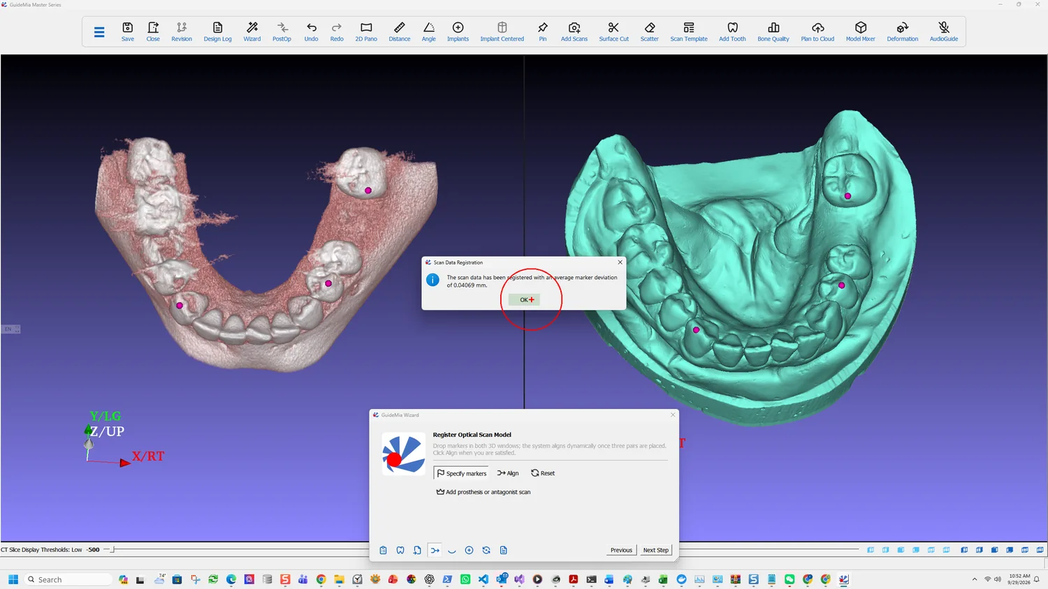
The registration result, reported as an average marker deviation

When it completes, the software tells you how well it did:

The scan data has been registered with an average marker deviation of 0.04069 mm.

Read that number. It is the average distance between your paired points after alignment, and it is the only quantitative feedback the step gives you. A figure in the hundredths of a millimetre, as here, means the markers agreed with each other. A figure an order of magnitude larger means one of them did not — and the remedy is to find the bad marker and remove it, not to add more.

What it does not tell you is whether you clicked the right anatomy. Three markers placed consistently on the wrong cusps will register beautifully and align the models wrongly. The number measures self-consistency; the check below measures correctness.

Checking it before moving on

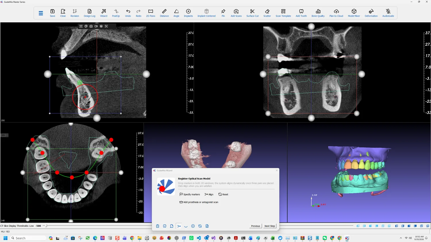
The registered result on the slice views

The 3D view is the least sensitive place to judge a registration. Two surfaces can look coincident and be half a millimetre apart.

Look at the 2D slices instead. The scan's outline is drawn over the CT, and a good registration has that outline following the enamel — sitting on the tooth surfaces rather than floating above them or cutting inside them. Step through several slices; an error that is invisible on one can be obvious two slices away.

The scan outline drawn over the CT slices

Check it where it matters most: at the teeth adjacent to the implant site, because those are what the guide will actually seat on.

This same outline is what you will be looking at again in fit analysis, from the other end: that step compares the finished guide against this registered model, so it can only be as truthful as this alignment is.

More on this page

The full Model Registration page carries tools the Wizard does not expose, and one of them answers the case where markers alone are not enough:

  • Fine-tuning of model position — step length and angle controls for the sagittal, coronal and axial views, which nudge a model by a set increment rather than by dragging. This is how you correct a registration that is nearly right, and it is only available on the full panel.
  • The same page handles registration of a radiographic guide, which follows a different route from an optical scan.

When a registration cannot be rescued, the cause is usually the scan rather than the markers. Go back to planning mode and right-click the scan template model to repair it — small holes and defects in a scan will also defeat the guide cut several steps later, so fixing it now saves the same problem twice.

Part One · step 6 of 18

Additional scans

The antagonist, the diagnostic setup and the pre-extraction model: what each one is for, and why the opposing arch matters before you place anything.

The arch is registered. This step brings in anything else the plan needs to be judged against — most often the opposing arch, sometimes a planned restoration.

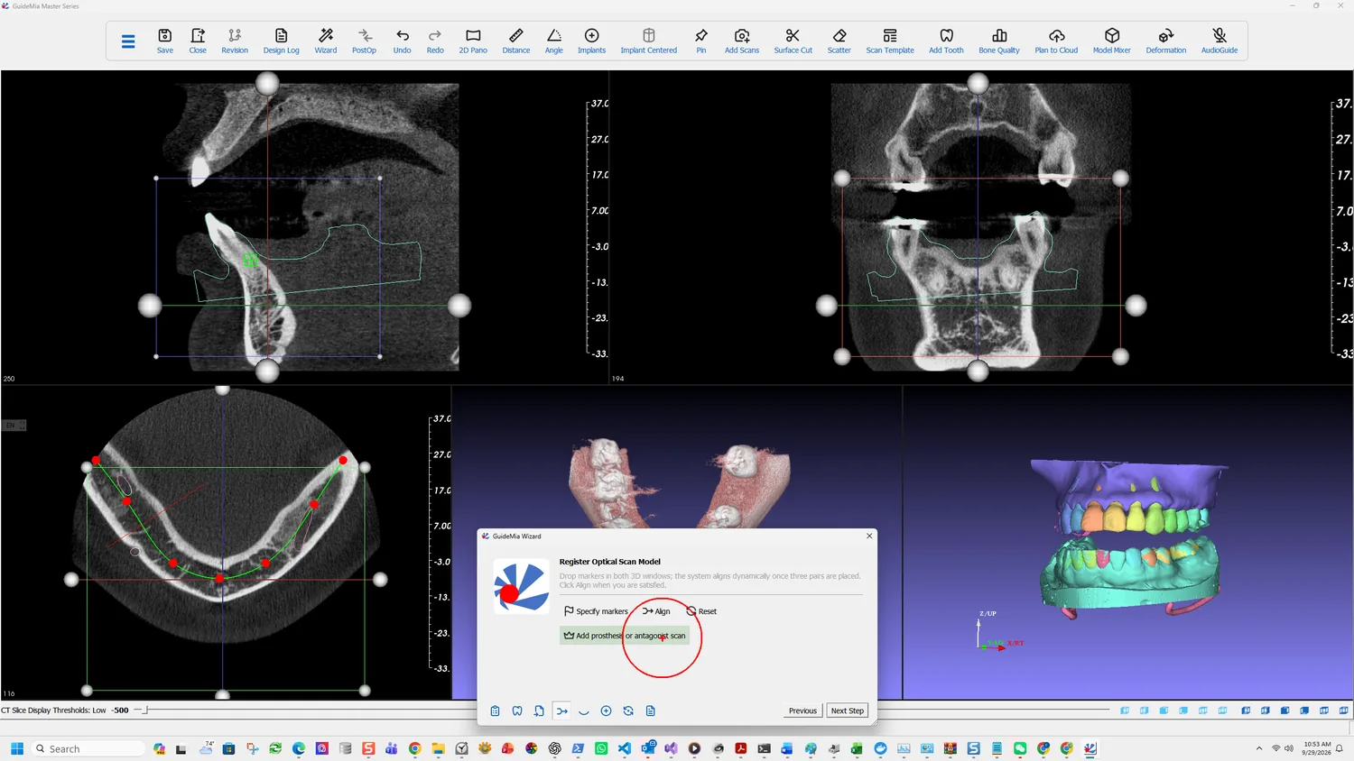
Add prosthesis or antagonist scan

What this loads, and the condition attached

Additional prosthesis model. It is required that the additional model has been registered with the current scan template that is being registered, so the additional scan will inherit the transformation from the scan template.

That condition is the whole mechanic. The additional model is not aligned independently — it inherits the transformation computed in the previous step. So it must already sit correctly relative to the scan template when it arrives.

In practice that means the two came out of the same scanner session, or the same design software, already in a shared coordinate system. A mesh from an unrelated source will land wherever its own origin puts it, and no amount of loading it again will fix that.

The two things people load here

An antagonist scan. The opposing arch, so the plan can be judged against the occlusion rather than against the working arch alone. This is what the demo case loads.

A tooth setup. The status tip gives the example directly:

Another example is your scan template is an intra-oral scan, and you have another STL file with tooth setup.

That is prosthetically driven planning in its plainest form: the restoration is designed first, loaded here, and the implant is then placed to serve it rather than the other way round.

Selecting the mesh file

The antagonist loaded against the working arch

Managing what is on screen

By this point the scene holds the bone, the segmented teeth, the registered scan and now the antagonist. That is more than you can usefully look at.

Hide removes an object from view without deleting it. It is the control you will use most from here on — hiding the antagonist to place the implant, then showing it again to check clearance. Objects are listed in the assembly window and in the Object Manager, and right-clicking one there is how you make it current, hide it, or act on it.

Working with objects hidden

More on this page

The full Additional References page in Case Preparation handles the same loading, alongside:

  • Denture design, loaded as a full-arch prosthesis rather than a single setup. GuideMia can add abutment holes to it, or generate a prosthesis guide — a guide the clinician seats to check occlusion and guide position before any drilling.
  • Virtual Tissue Model, for cases needing the soft tissue represented explicitly rather than inferred from the scan surface.

The Add Scans toolbar button reaches these without the Wizard.

One planning note that belongs here rather than later: if you intend to place the implant against a restoration, load the restoration now. Placing first and loading the setup afterwards works, but it invites the quiet mistake of planning to the bone and then discovering the restoration wanted the fixture somewhere else.

Part One · step 7 of 18

Placing the implant

Pick the tooth, choose the fixture from the library, judge it on all three planes, and set the surgical kit, sleeve and depth the guide will be built from.

This is the step the whole case exists for. Everything before it prepared the anatomy; everything after it builds hardware around the decision made here.

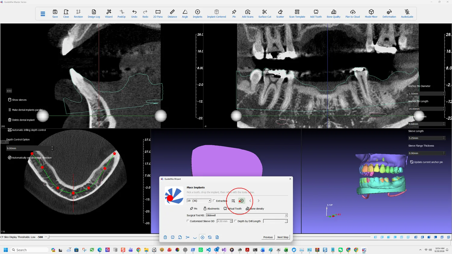
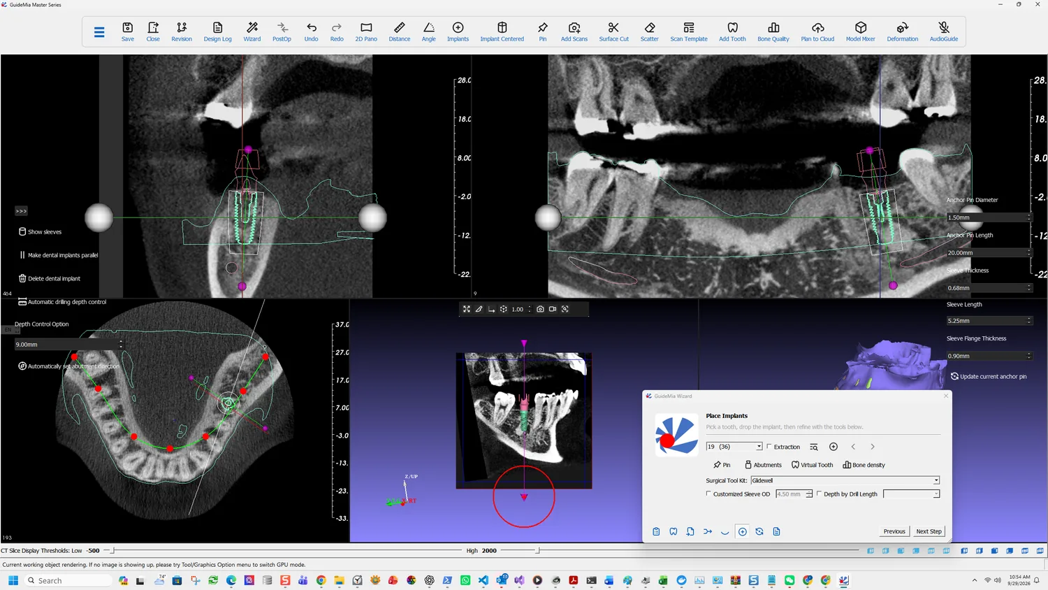
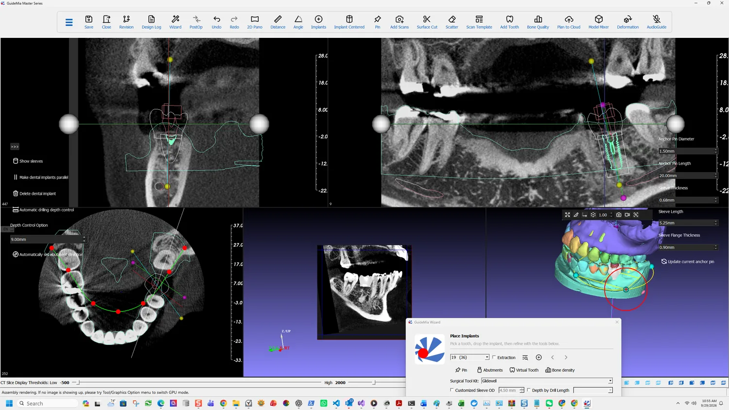
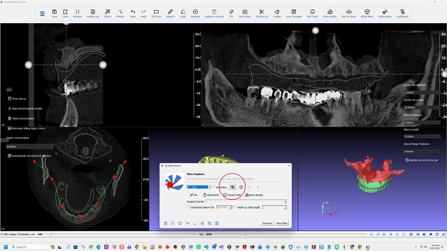
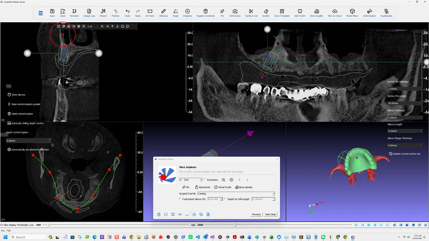
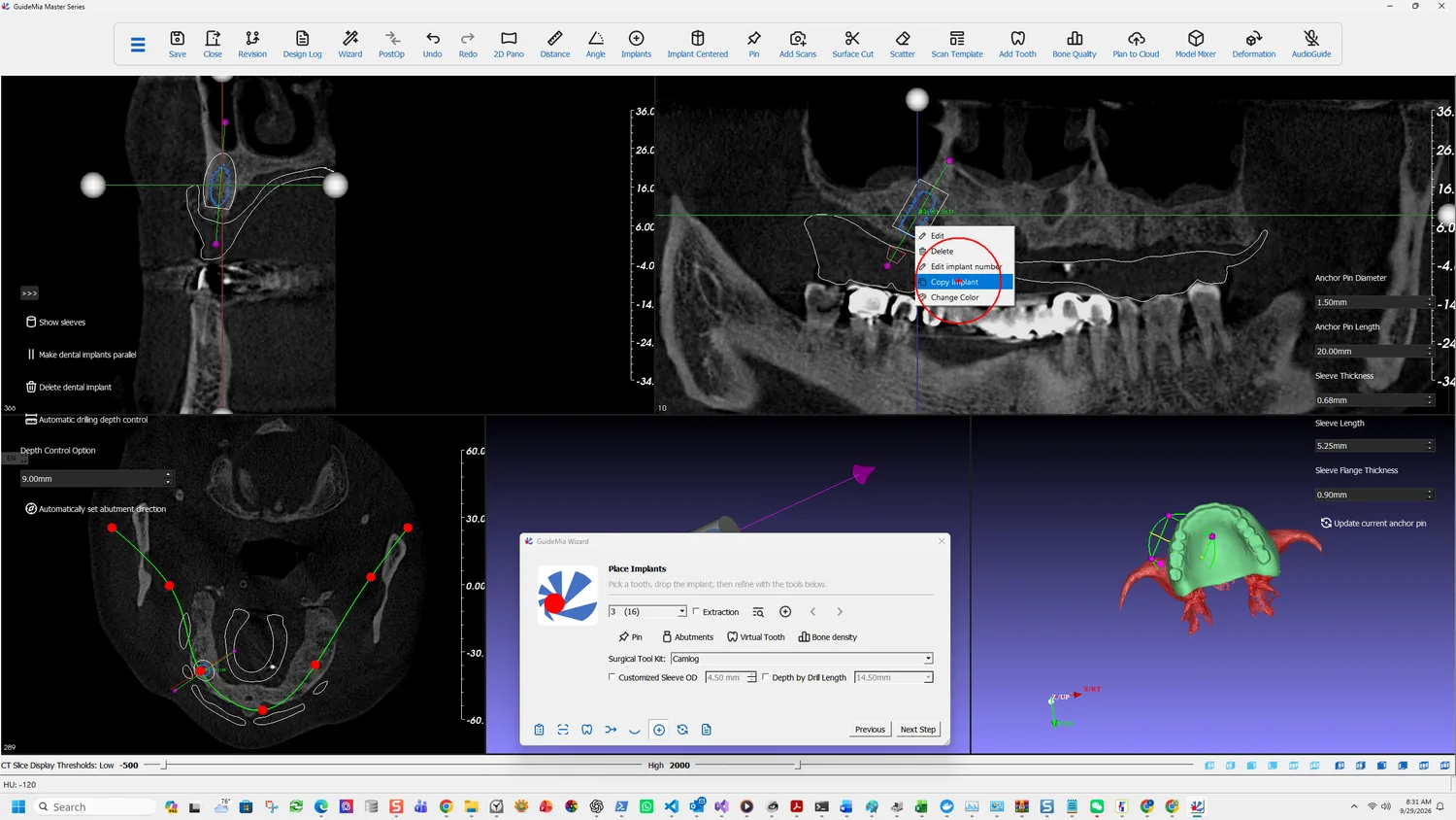
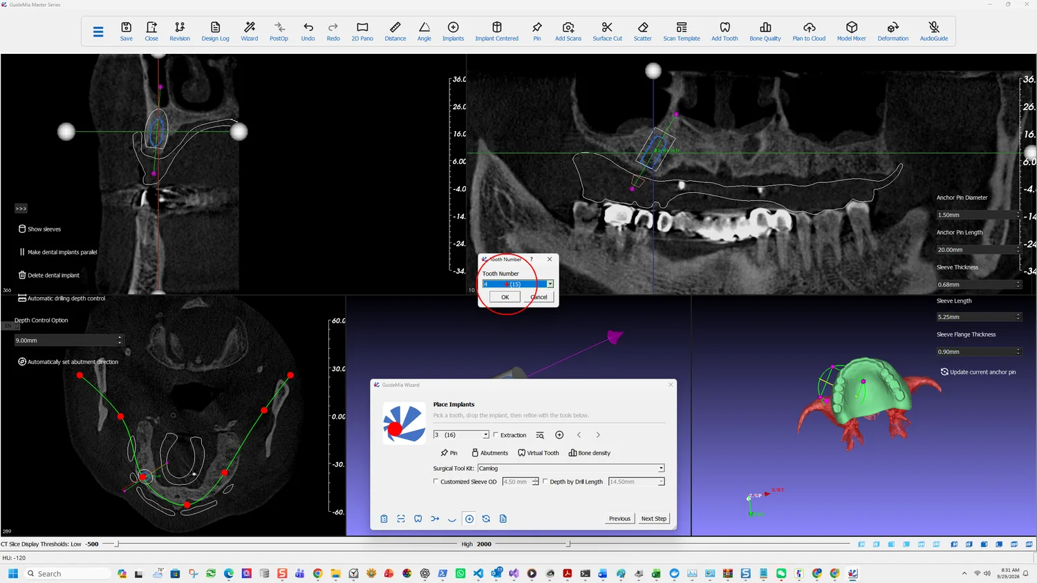
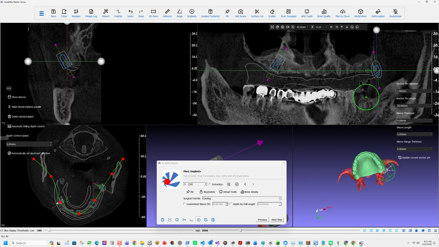
Place Implants, with the tooth chosen and Browse about to open the library

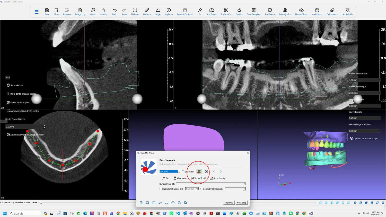
The Wizard reduces it to a sentence: "Pick a tooth, drop the implant, then refine with the tools below."

Pick the tooth

The tooth number list drives the page. Selecting a number either edits the implant already at that site or starts a new one — the page's own status tip says so: "Select a tooth number to edit an existing implant or to create a new one." In this case it reads 19 (36), the universal number with the FDI number beside it.

Extraction is not a note to yourself. It changes what the guide can rest on:

This option will tell the system that the tooth with given number will be extracted at treatment time. The extraction option essentially tells the system that the tooth surface of the implant site will be gone, and it cannot provide support to the surgical guide. Accordingly, GuideMia will add materials in this side to design the surgical guide.

Tick it for an immediate-placement case and the guide is designed differently. Forget it and the guide is built to seat on a tooth that will not be there when the guide is used.

Choose the fixture

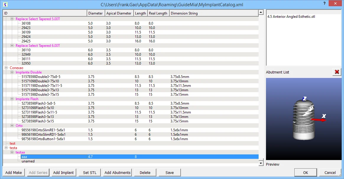
Browse opens the system implant library. The library ships with a long list of manufacturers; if yours is not among them, it can be added.

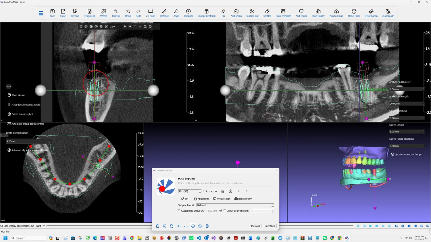
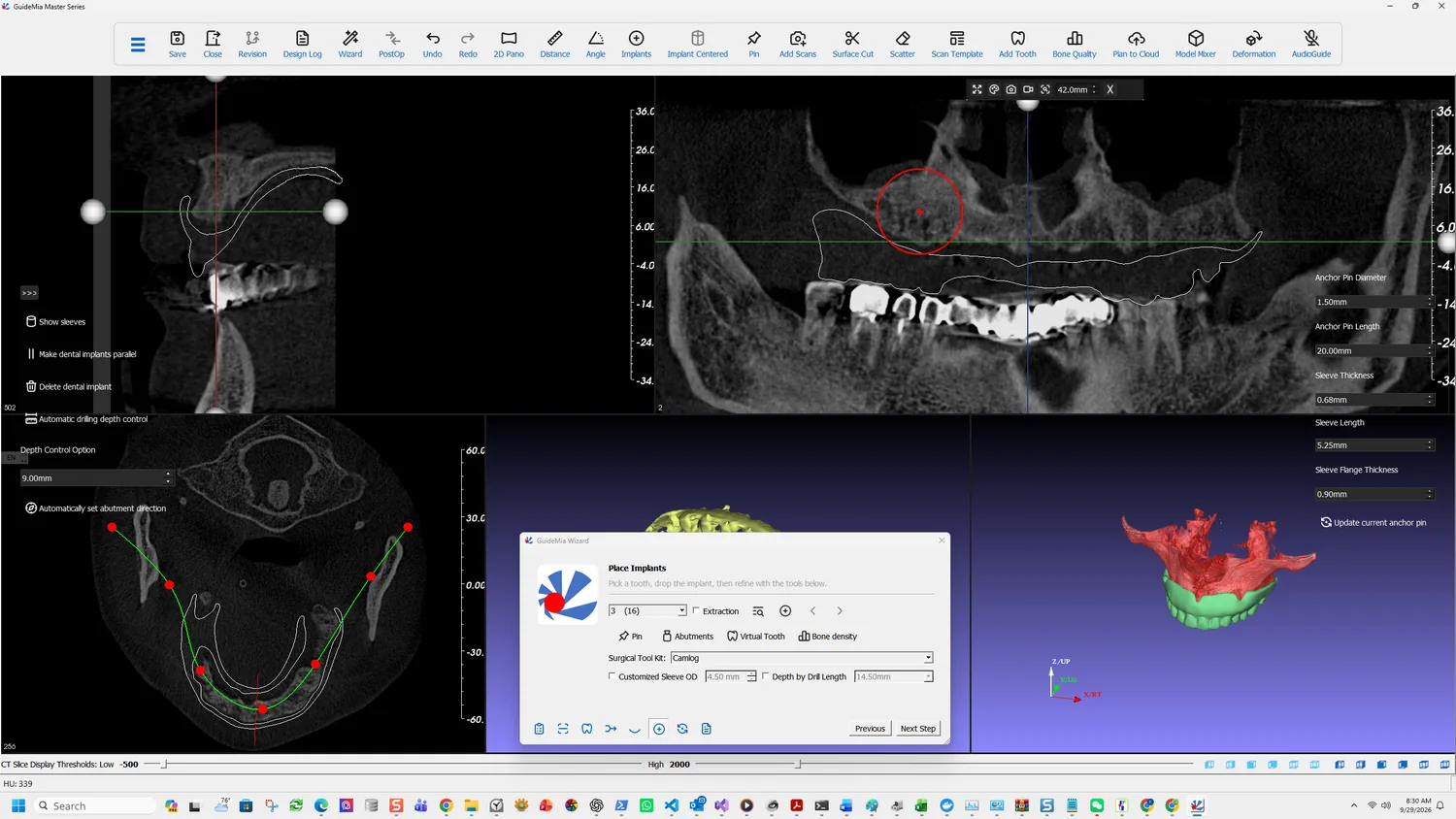
The fixture placed, seen across the slice views

With an implant chosen, click where you want it in any image window — 2D slice or 3D — and it is placed there.

Add/Update Implant does double duty, and the second half is the one that gets missed:

Add or update current implant. To add implant, click at wherever you want to add implant in any image window. If you change any parameters or options of the current implant, use this button to update.

Change a diameter, a length, an option — nothing happens until you update. The screen will keep showing the old geometry and it looks like the change was ignored.

Previous / Next Implant step between fixtures. A single-unit case has one; a full arch is where these earn their place.

Judge it on all three planes

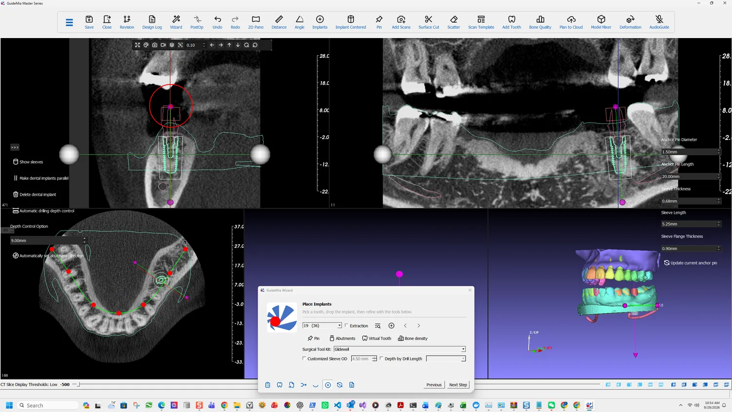
Checking the fixture on the coronal view

A position that looks right on one plane is routinely wrong on another. The sagittal view shows the angulation relative to the ridge and the opposing arch; the coronal shows the buccolingual position and the distance to the canal; the axial shows where it sits along the arch relative to its neighbours.

The sagittal view

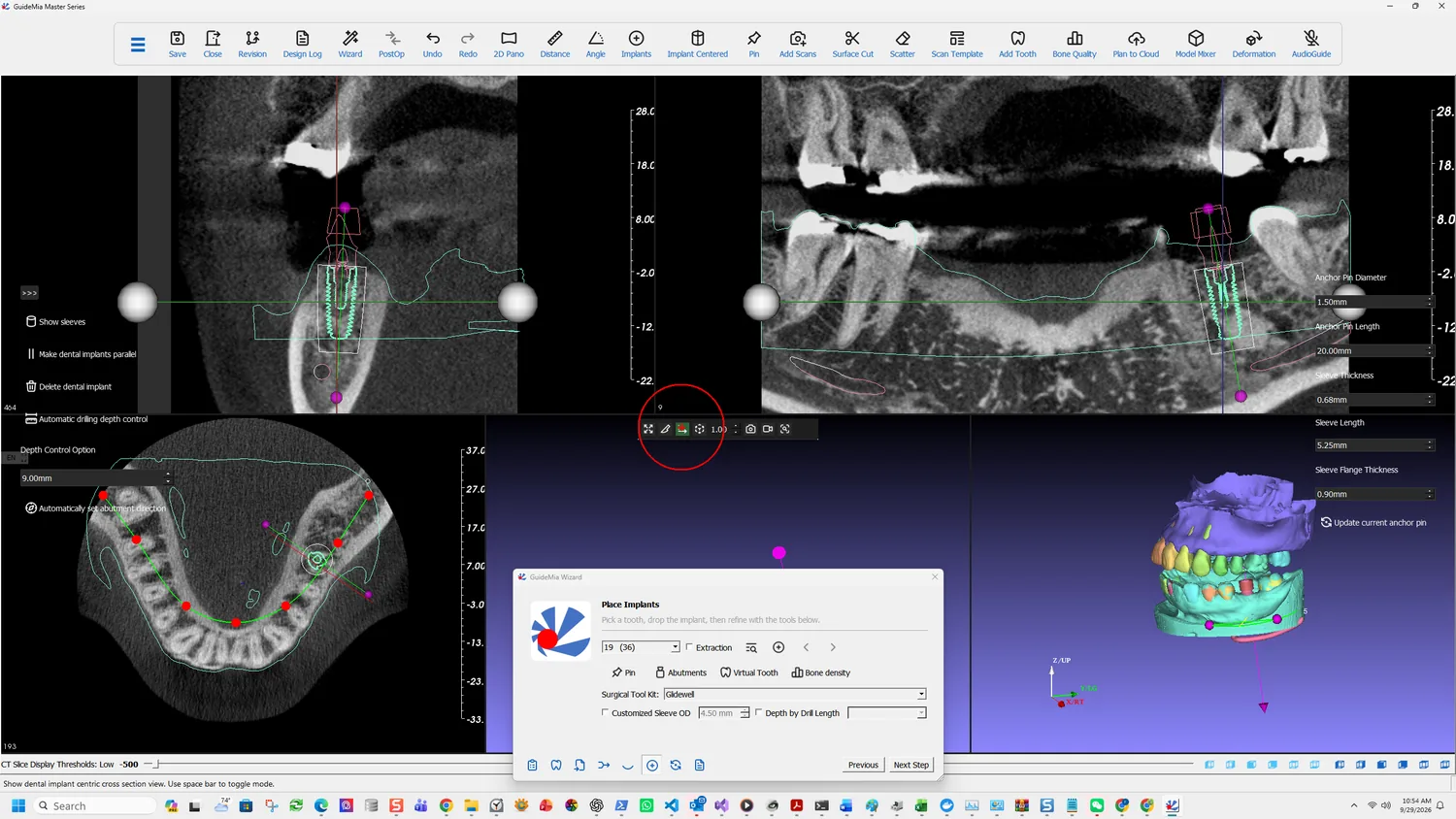
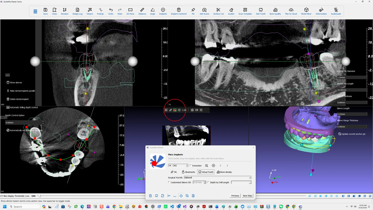
Show dental implant centric cross section view reorients the slices around the implant rather than around the volume's own axes:

Show dental implant centric cross section view. Use space bar to toggle mode.

That is the view to judge angulation in, because the slice is taken through the fixture rather than through the scan. The space bar toggle is worth learning — you will move between the two constantly.

The implant-centric cross section

Bone density turns on neighbourhood inspection: "In the working window use mouse wheel to inspect implant neighborhood." The mouse wheel walks you through the bone immediately around the fixture, which is how you find out whether the apex is sitting in something that will hold it.

Inspecting the site in 3D

The sidebar tools

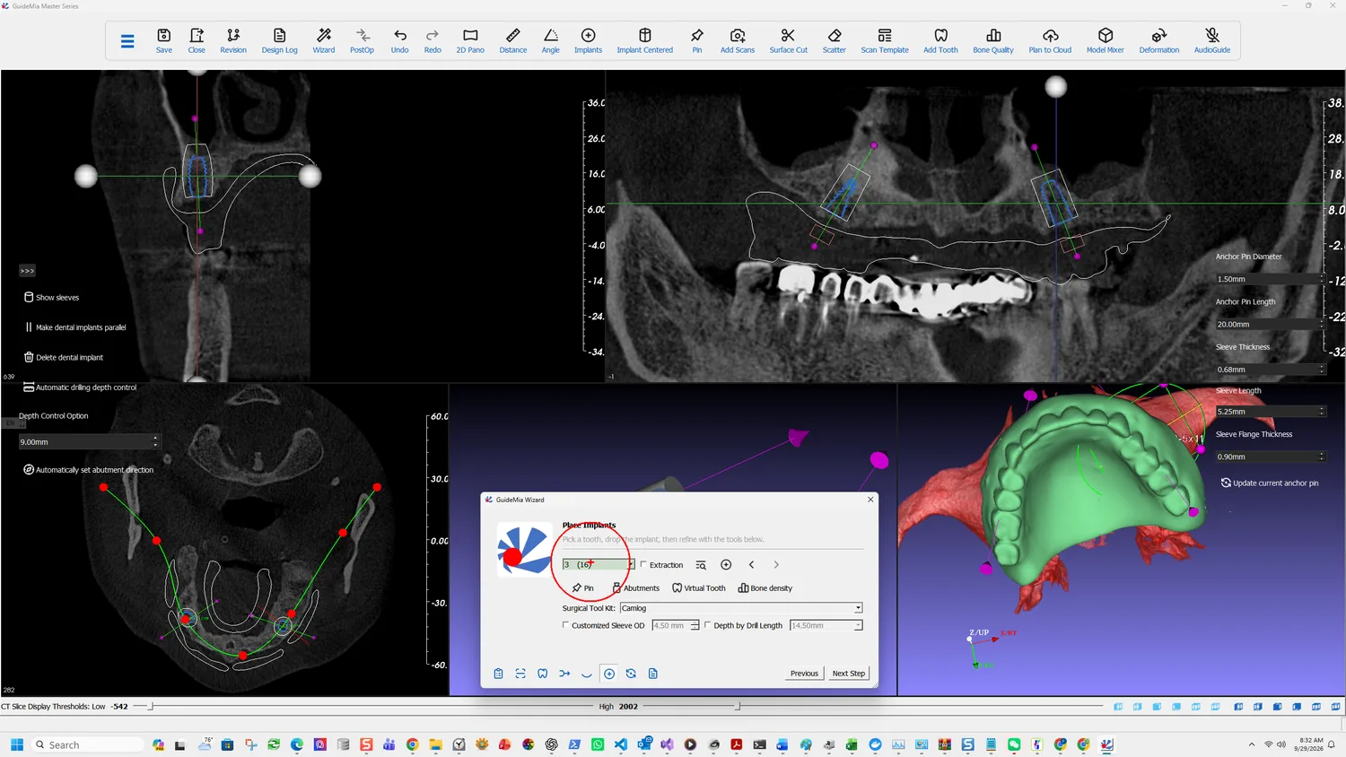
  • Show sleeves displays the sleeves the current kit will produce, in place. Worth turning on before you are satisfied with the position, because a sleeve is considerably larger than the fixture and can collide with a neighbouring tooth when the implant itself does not.
  • Make dental implants parallel aligns multiple fixtures. Irrelevant to a single unit, essential to a full arch.
  • Delete dental implant removes the current one.
  • Automatic drilling depth control, with a Depth Control Option in millimetres — 9.00 mm here.
  • Automatically set abutment direction derives the abutment orientation rather than leaving it to be set by hand.

Set what the guide will be built from

The three controls at the bottom of the page are not planning aids. They determine the geometry of the guide generated later.

Surgical Tool Kit picks the kit whose sleeves and drills the guide must match:

Some implant brands have corresponding surgical tool kits, some don't. When a first implant is added, the system will try to match and set this surgical tool kit. If there is not matched kit, the system will use GuideMia universal kit as default.

So it is usually set for you by the implant you chose. When it is not, you get the GuideMia Universal Kit, which is a real kit with real sleeve diameters rather than a placeholder. A kit of your own can be defined.

Customized Sleeve OD overrides the sleeve outer diameter the kit would supply. Depth by Drill Length sets the total drill length directly instead of deriving it — "You can set the total drill length as you like."

Change either here, before the guide is generated, not after.

The panel on the right carries the anchor pin and sleeve dimensions the guide will be built to: pin diameter and length, sleeve thickness, sleeve length and sleeve flange thickness, with Update current anchor pin to apply a change.

More on this page

The full Place Implants page splits into Implant, Abutment, Sleeve and Depth Control tabs, where the Wizard shows one combined panel. Alongside it in Treatment Planning:

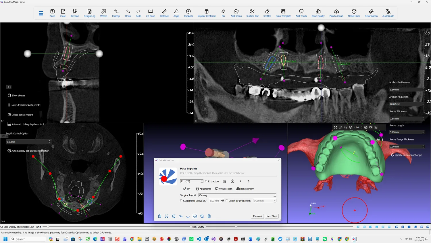
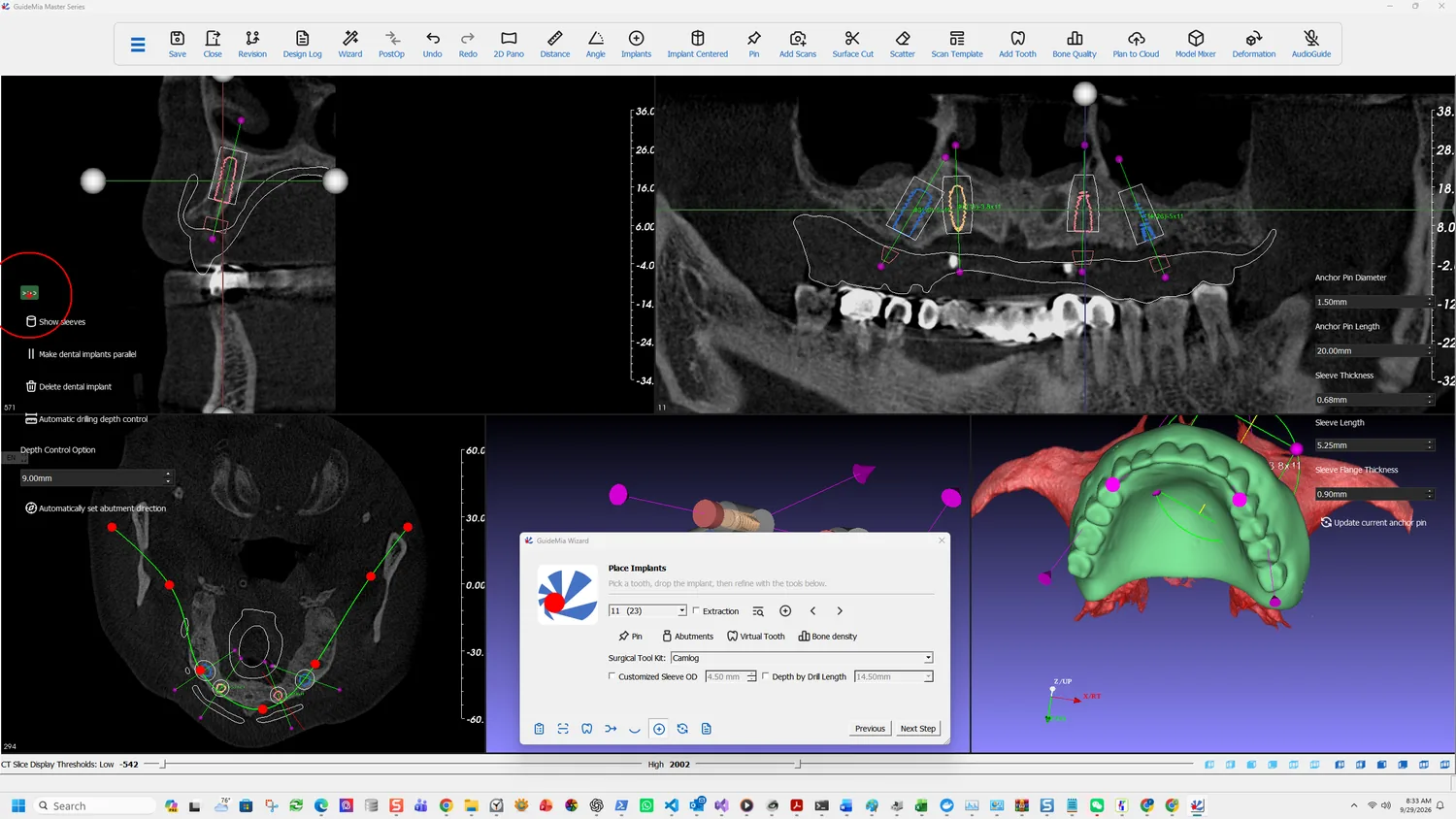
  • Anchor Pins or Screws — a page of its own. Pin on the Wizard adds one by clicking a site in any image window, after which it can be moved and rotated, and "when the pin is too close to implants or other pins, it will turn red."
  • Bone Reduction or Combined Guide Splitting — where a case needs the ridge reduced before placement. V6 moved the bone reduction design here, leaving only the guide half in guide design.
  • Bone/Sinus Graft.
  • Plan Error Simulation — models the effect of a deviation on the planned position, which is the honest way to decide whether a plan has enough margin.

Positioning by abutments is worth knowing if you use custom abutments: right-click an implant in the assembly window and the placement tool moves onto the abutment rather than the fixture, so you adjust the implant by moving the restoration. The parallel tool on the coronal view's context menu then makes abutments parallel rather than fixtures.

Part One · step 8 of 18

The virtual tooth, and reviewing the plan

Put the restoration on the plan, check it against the opposing arch, and satisfy yourself on bone, canal, restoration and occlusion before any geometry is built.

The fixture is placed. Before committing to a guide, this step asks the question the plan has to survive: does the implant serve the restoration, and does it work against the opposing arch?

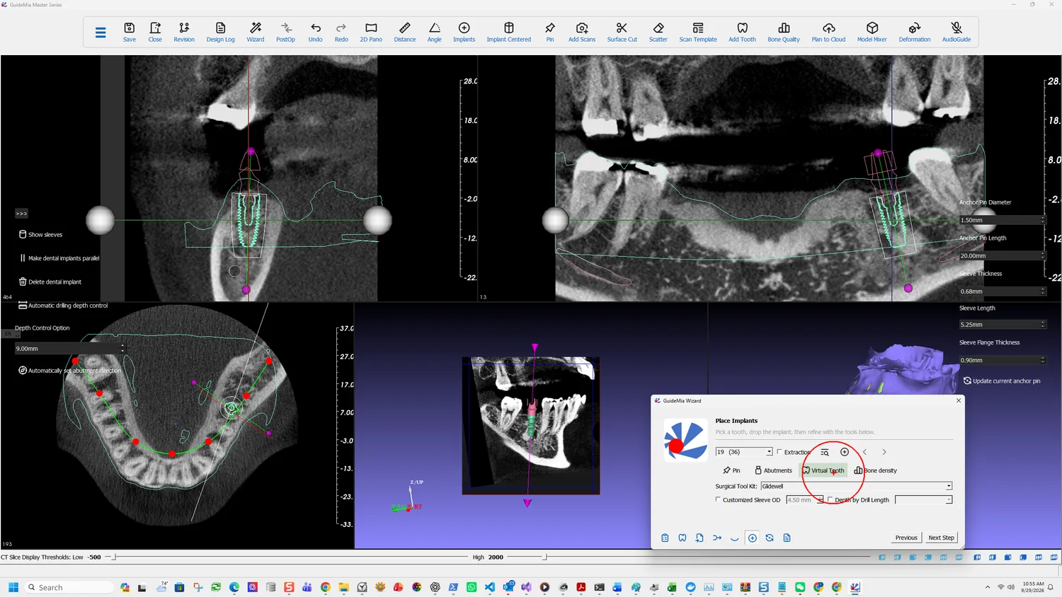
Add Virtual Tooth

Put the restoration on the plan

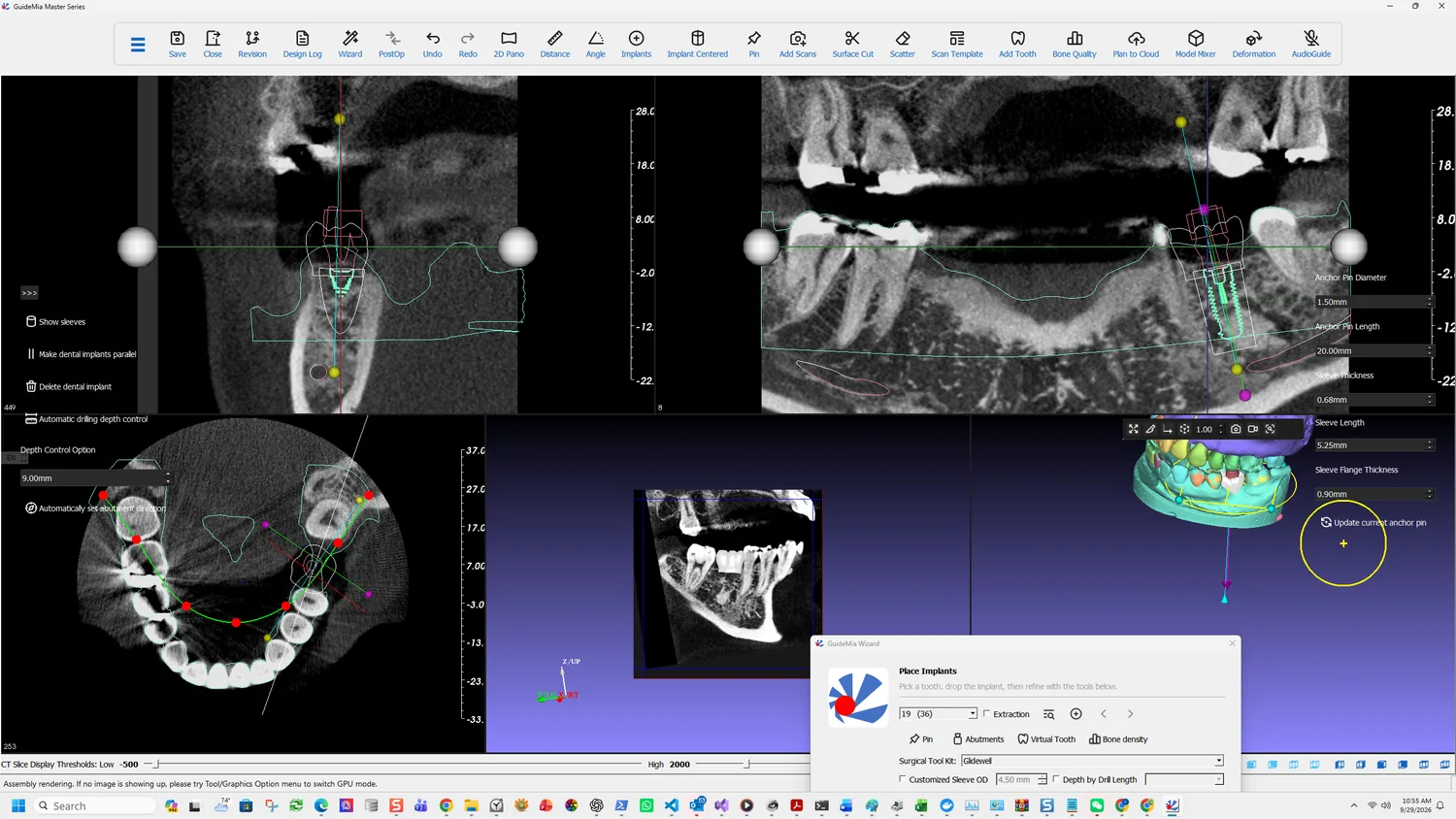
Virtual Tooth places a tooth model at the site so the plan can be judged against what will eventually be there:

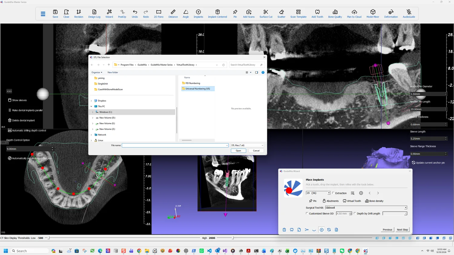
Add tooth STL models. GuideMia has a set of tooth templates. You can also use your designs.

So there are two routes — the shipped templates, or your own STL from wherever you design crowns. The file dialog takes either.

One caution comes with it, and it is worth reading before anyone builds on the output:

Please be advised this virtual tooth function is for visualization and treatment planning purposes. It may or may not meet the need to make temporary restoration from it.

It is a planning object, not a restoration. If a provisional is wanted, design it properly elsewhere.

Selecting a tooth model

Local and global deformation tools adjust the shape and size of a tooth model once placed, so a template can be made to fit the space rather than being accepted as it comes.

The virtual tooth in place

Judge the plan against it

This is where prosthetically driven planning becomes concrete rather than a phrase. With the tooth in place you can see whether the fixture emerges where the restoration needs it, or whether the plan is bone-driven and the restoration will have to compensate.

Reviewing the plan in 3D

If the answer is wrong, go back to implant placement and move it. The cost of moving a fixture at this stage is nothing; the cost after the guide is generated is regenerating it, and after surgery it is not recoverable.

Bring in the antagonist

The antagonist scan shown against the plan

The opposing arch loaded earlier is what tells you whether there is room. Show it and look at the occlusal clearance over the planned restoration — a fixture that is ideal in the bone and leaves four millimetres of clearance has a problem that only appears here.

Show in 2D brings an object into the slice views rather than leaving it in 3D only:

Show in 2D

That matters for judging clearance, because a 3D view of two surfaces tells you they do not intersect but not by how much. On a slice you can see the gap and, with the measurement tools on the toolbar, put a number on it.

Check it one more way

The implant-centric cross section, used for the final check

Show dental implant centric cross section view again, with everything now loaded — fixture, restoration, antagonist, nerve. This is the single view that carries the whole decision, and it is the one to sit on before moving to guide design.

Four things to satisfy yourself about before the next step:

  • Bone. Adequate width and length, with the apex in something that will hold.
  • The canal. Clearance to the mandibular nerve, judged on a slice rather than in 3D.
  • The restoration. The fixture emerges where the tooth needs it.
  • The occlusion. There is room for the restoration against the opposing arch.

Guide design validates the plan before it builds anything — the status bar says so — but it validates geometry, not judgement. These four are yours.

More on this page

The toolbar carries the measurement tools this step wants: Distance and Angle, and 2D Pano for a panoramic reconstruction along the arch curve.

Bone Quality maps bone density to colours across the model, which is a faster way to survey a site than walking it with the mouse wheel.

Plan Error Simulation, on the Treatment Planning page, models what a deviation does to the planned position. If the margins in the four checks above are tight, this is the tool that tells you whether the plan tolerates a real surgical error or only a perfect one.

Save Revision stores the plan — the implants and their positions — under the case. A second plan can then be built and Switch to selected plan moves between them, which is how two options are prepared for a discussion rather than one being overwritten by the other.

Part One · step 9 of 18

Designing the guide

Set the insertion direction from the view, outline the guide base, cut it, choose thickness and sleeve system, and generate — an outline that survives a change of plan.

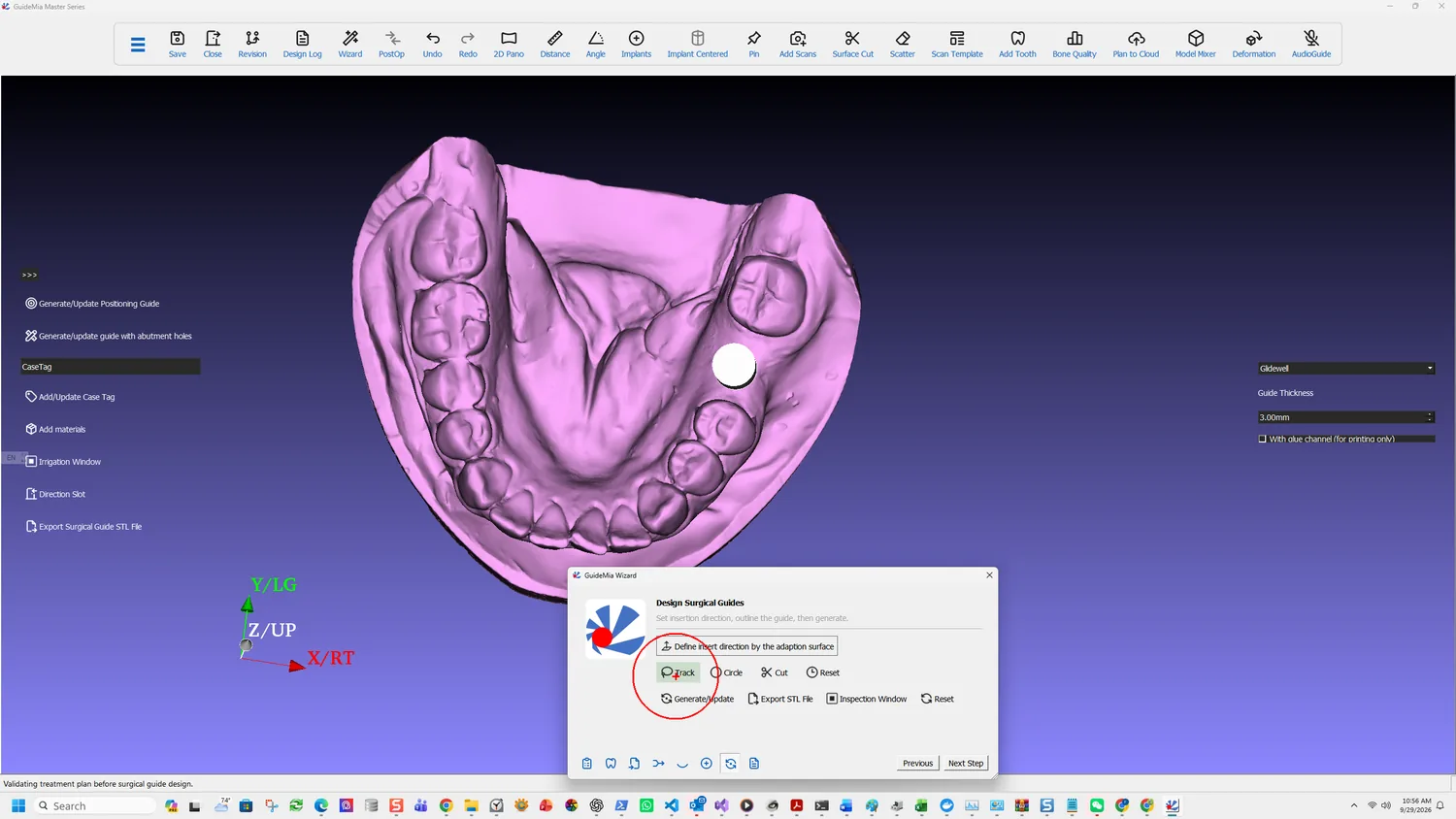
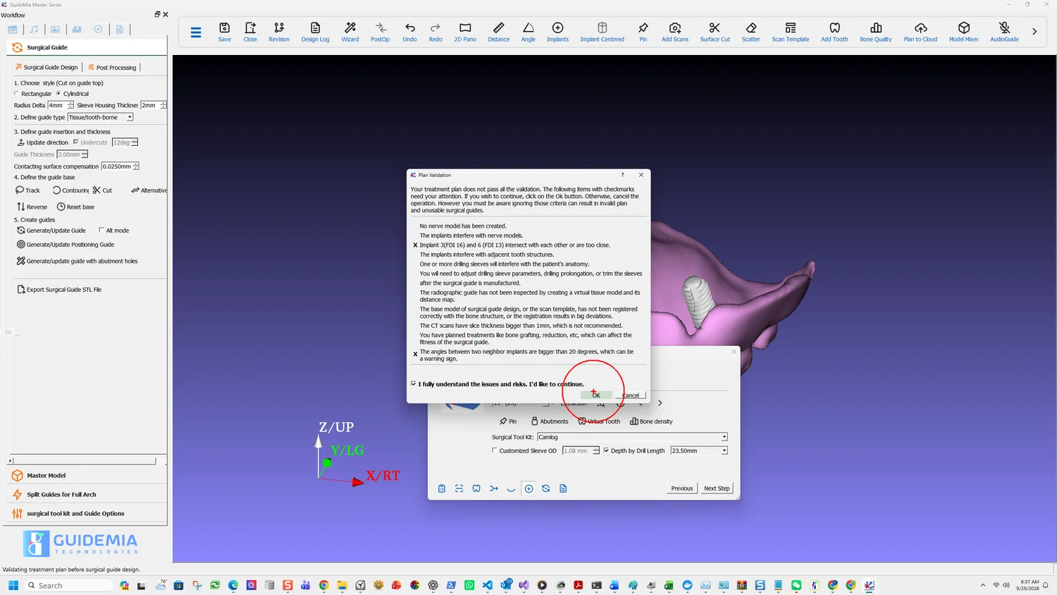
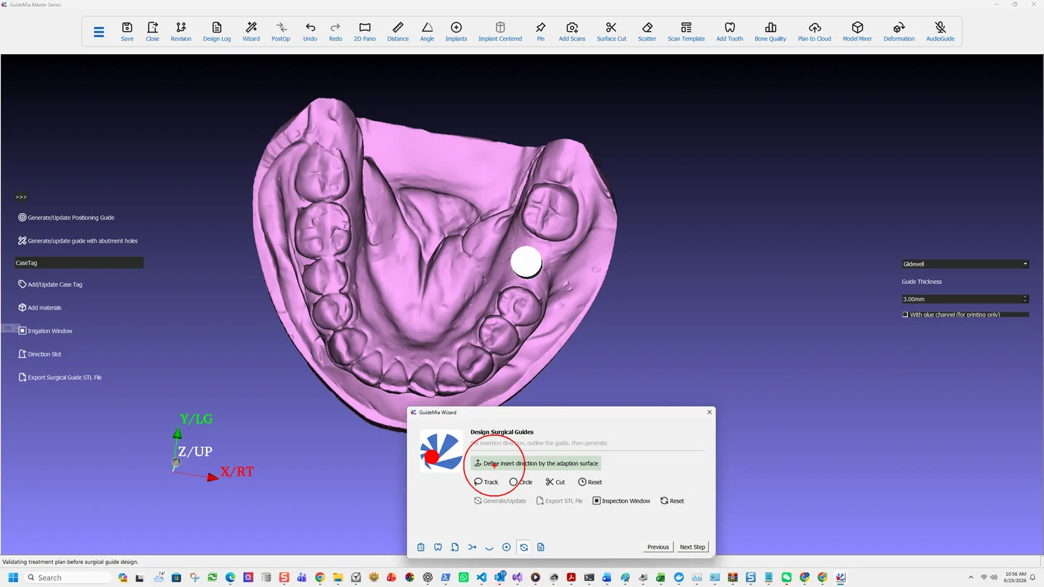
The plan becomes an object here. The Wizard reduces it to three acts — "Set insertion direction, outline the guide, then generate" — and the status bar names what happens underneath: "Validating treatment plan before surgical guide design." The plan is checked before any geometry is built.

Entering guide design

Set the insertion direction

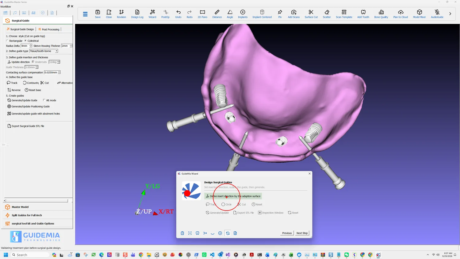
Define insert direction by the adaption surface

Define insert direction by the adaption surface takes the direction from how you are looking at the model. Its status tip is four words and they are the whole mechanic:

Update insert direction as view normal

So orient the view the way the guide will seat, then click. There is no numerical entry and no separate dialog; the camera is the input.

Getting it wrong does not fail immediately. It surfaces two steps later, when Cut returns the occlusal side of the model instead of the gingival one, and the cause is not obvious from the symptom.

Outline the guide

Two tools do the same job by different means. Both work from a bone model or an optical scan; neither is for radiographic guides.

Tracking the boundary

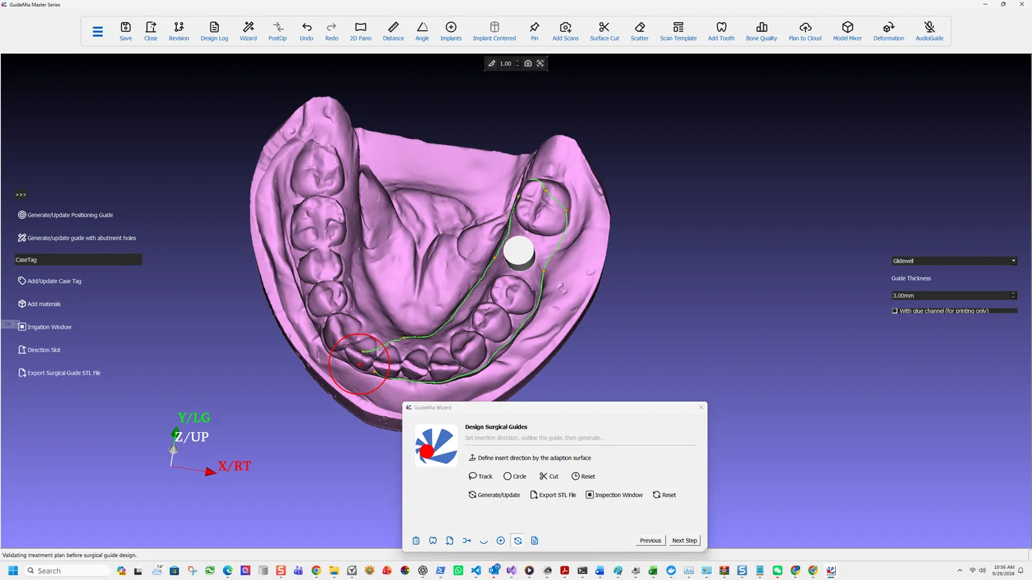
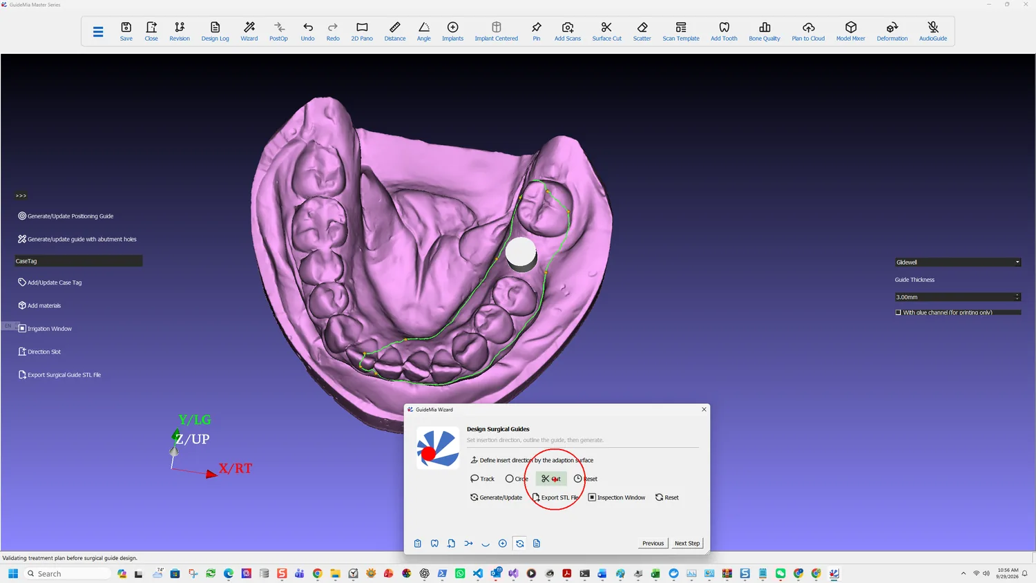
Track is the usual one. Select points on the base model and they connect into a boundary; click the first point again to close it. Two handling notes, both easy to trip over:

If you even need to rotate the view, move your mouse out of the model area and then rotate using the left button. Do not use right mouse button during the process. If you do so, it will stop, you can click the button again to redefine the boundary.

So: rotate only from outside the model, and never right-click. Right-clicking abandons the boundary and you start it again.

The boundary closed

Circle is the alternative for when Track will not cut. It draws a profile on the display plane, and the direction you draw in is meaningful:

When you draw the profile clockwise, the area within the profile will be kept. If you go anti clock wise, the circled area will be trimmed away.

Expect to work in passes with it — define a profile, Cut, rotate, cut again.

Cut

After Cut, the guide base isolated in teal

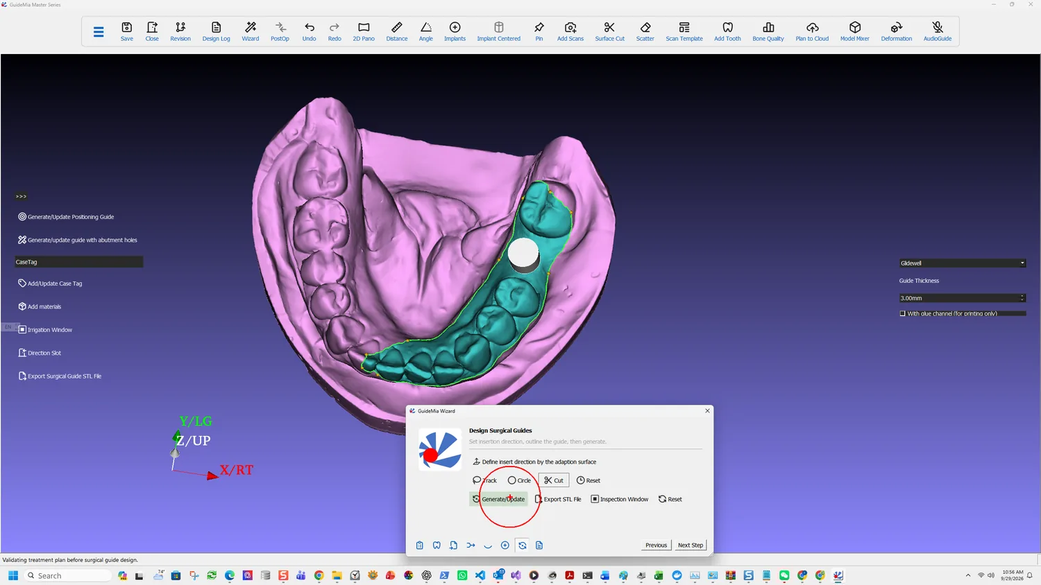
Cut applies the boundary, selecting the area inside it. Three outcomes and what each means:

It selects the right area. Carry on.

It selects the wrong side. Take the alternative area with the button to its right, rather than redrawing.

It fails. The software points at the cause:

If this operation fails, you need to consider fix the base model or use the Circle tool. If an optical scan has quality issues, small holes, etc, this operation may fail. Go back to planning mode, right click on the scan template model to fix it.

A scan defect that was invisible at registration shows up here. This is the same fault described in registering the scan — which is why looking at the scan before registering it is worth the minute.

Reset clears the guide base definition so it can be defined again.

Set what the guide is made of

The panel on the right decides the physical object rather than its outline:

  • The implant system the sleeves must match — Glidewell in this case, following the surgical kit set during planning.
  • Guide Thickness — 3.00 mm here.
  • With glue channel, which is for printing only.

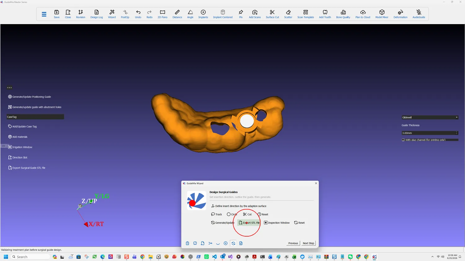
The sidebar carries the variants and the finishing work: Generate/Update Positioning Guide, Generate/update guide with abutment holes, Add/Update Case Tag, Add materials, Irrigation Window, Direction Slot and Export Surgical Guide STL File.

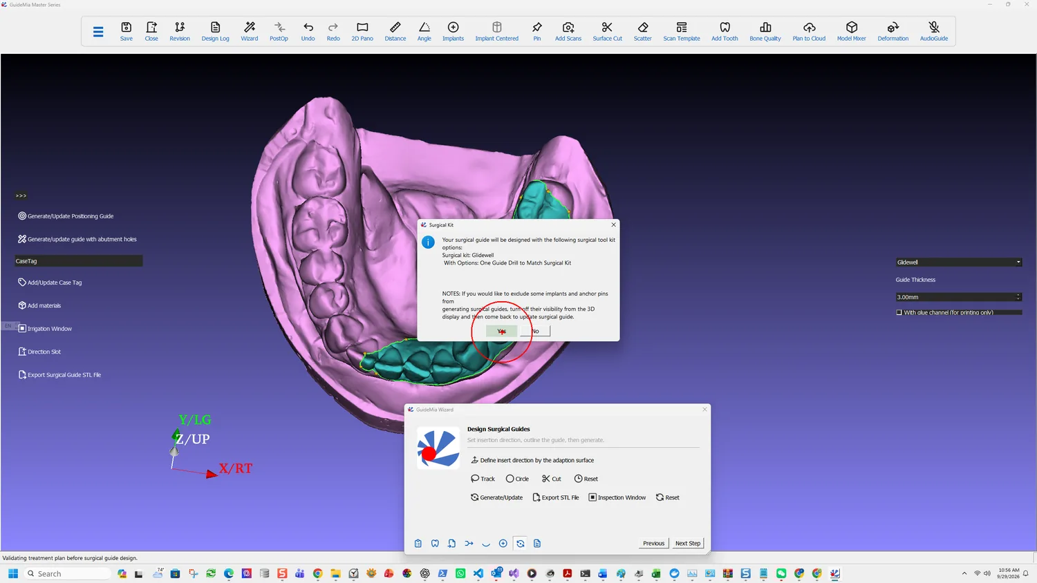
Generate

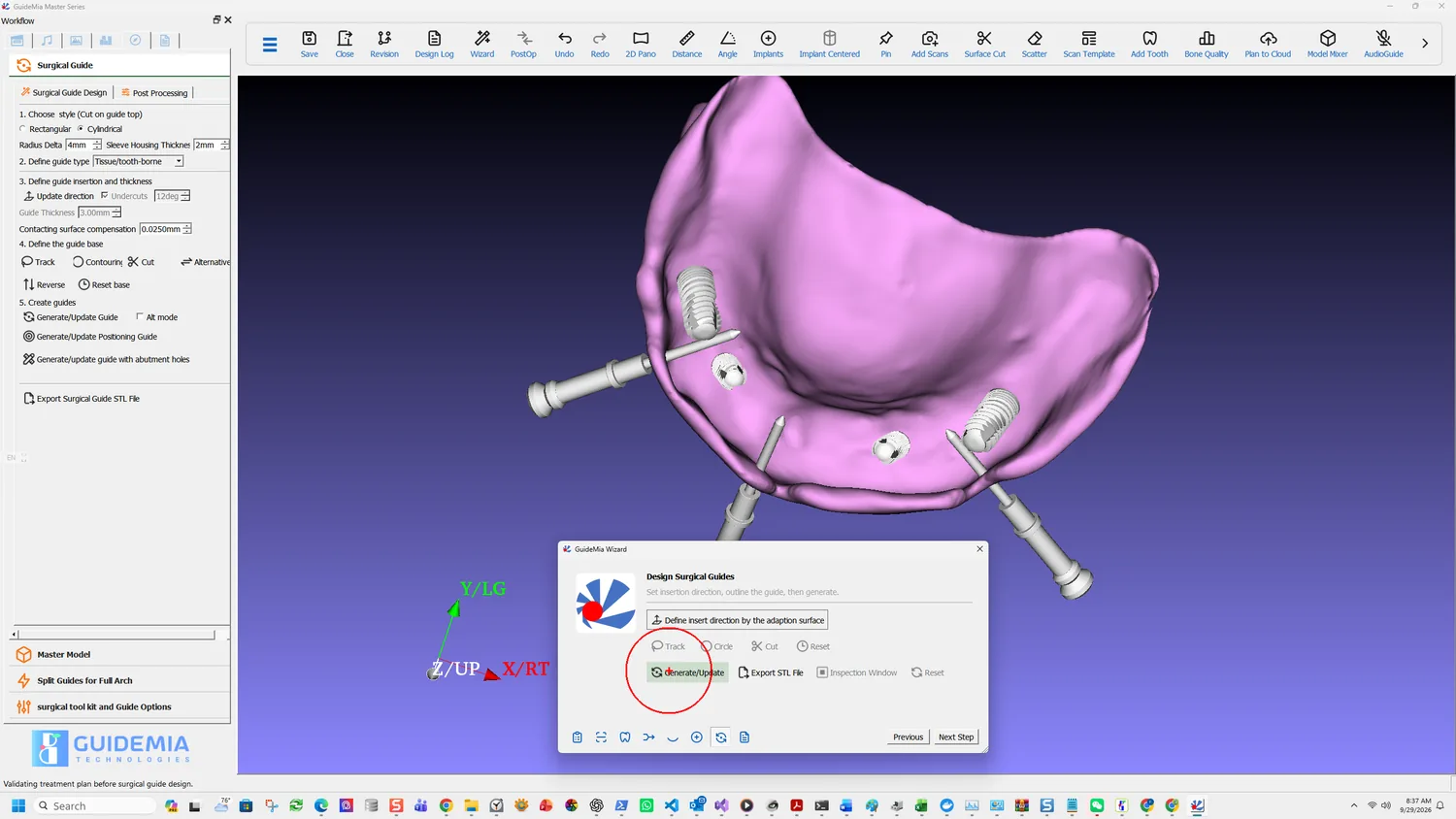
Generate/Update

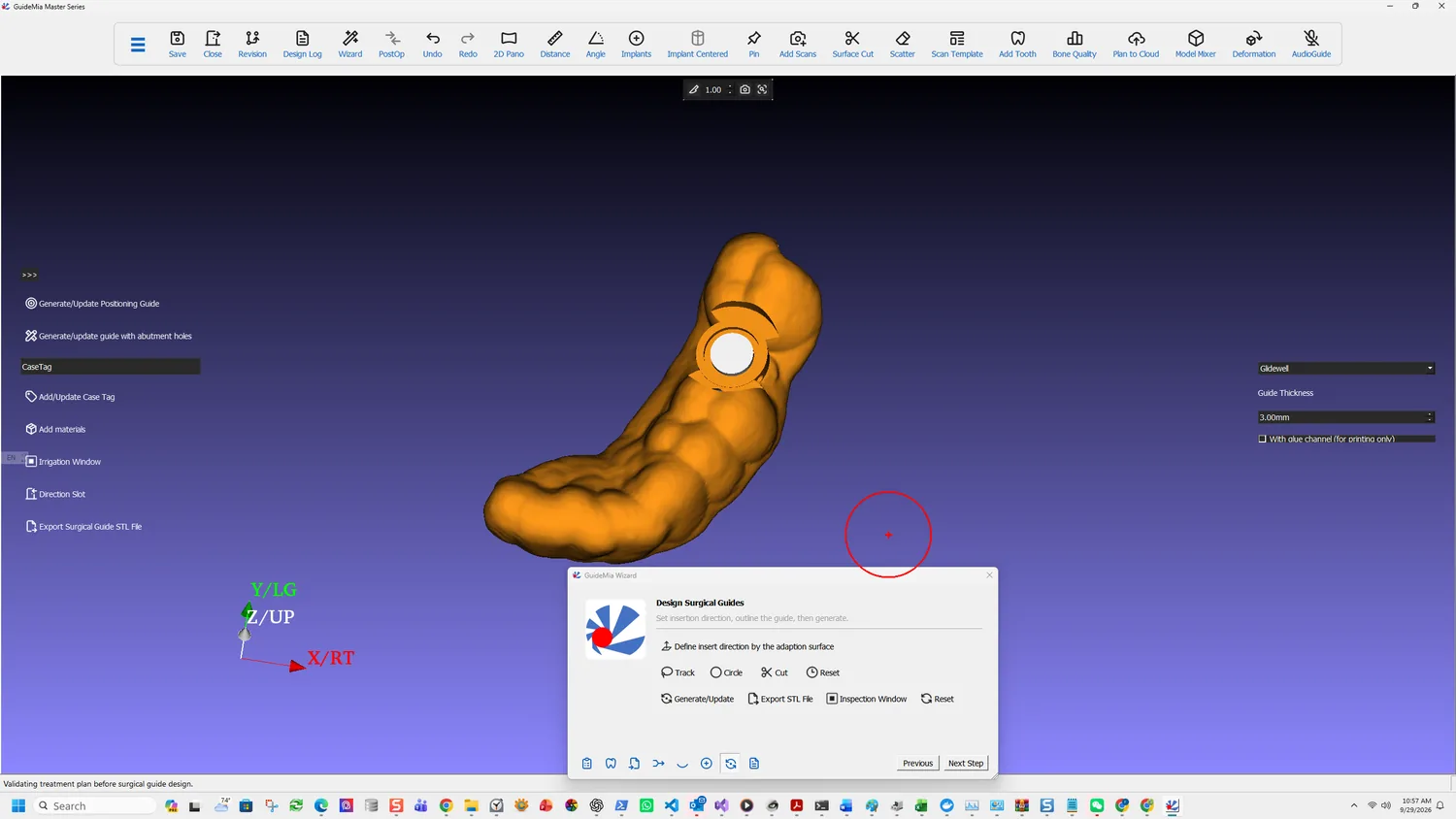
Generate/Update builds the guide — and it is also how you revise one:

In case the guide base has been defined, and you go back to the planning page to adjust Dental Implant positions or other options, you can come back here and click to update guides. This function works for all the surgical guide types. In case of bone reduction guides, plateau guides and combined guides, this will generate all guides together.

That is the sentence worth remembering: the outline survives a change of plan. Move an implant, come back here, update. You do not re-trace the boundary.

And for a case with several guide types, one click generates them all rather than each in turn.

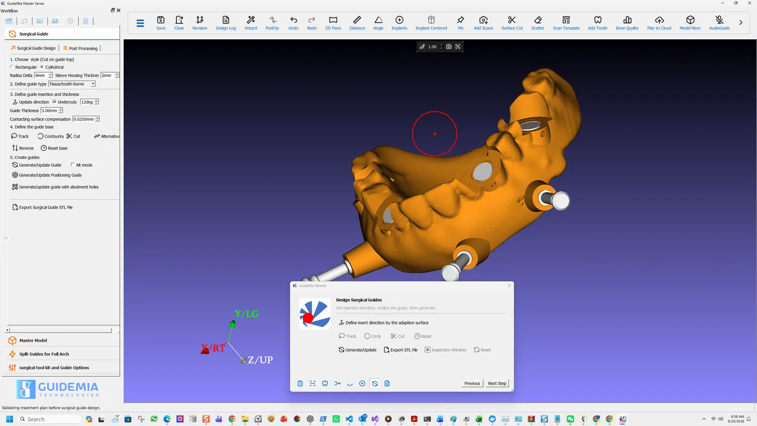
The generated guide

More on this page

The Surgical Guide Design group in the workflow panel carries what follows generation:

  • Post Processing — the finishing operations applied to a generated guide.
  • Master Model — for producing a model alongside the guide.
  • Split Guides for Full Arch — dividing a full-arch guide into sections that can be printed and seated. Not relevant to a single unit; essential when the span is long.
  • Surgical tool kit and Guide Options — the same kit and sleeve parameters reachable from planning, so a guide option can be revised without going back.

Guide types beyond the ordinary one, all generated by the same button: positioning guides, guides with abutment holes, bone reduction guides, plateau guides, hybrid guides and tooth-supported guides. The tooth-supported route is the CT-only case described in choosing the case type — on entering guide design the system asks whether to design a purely tooth-level guide, and answering yes builds clearance cylinders between the guide and the bone and tooth model so the guide seats on the neighbouring teeth.

Part One · step 10 of 18

Inspection and irrigation windows

The two openings cut into every guide: one so the surgeon can confirm it is seated, the other so the bone survives the drilling.

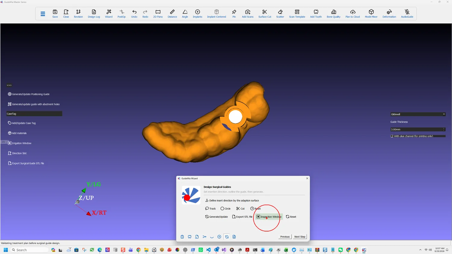
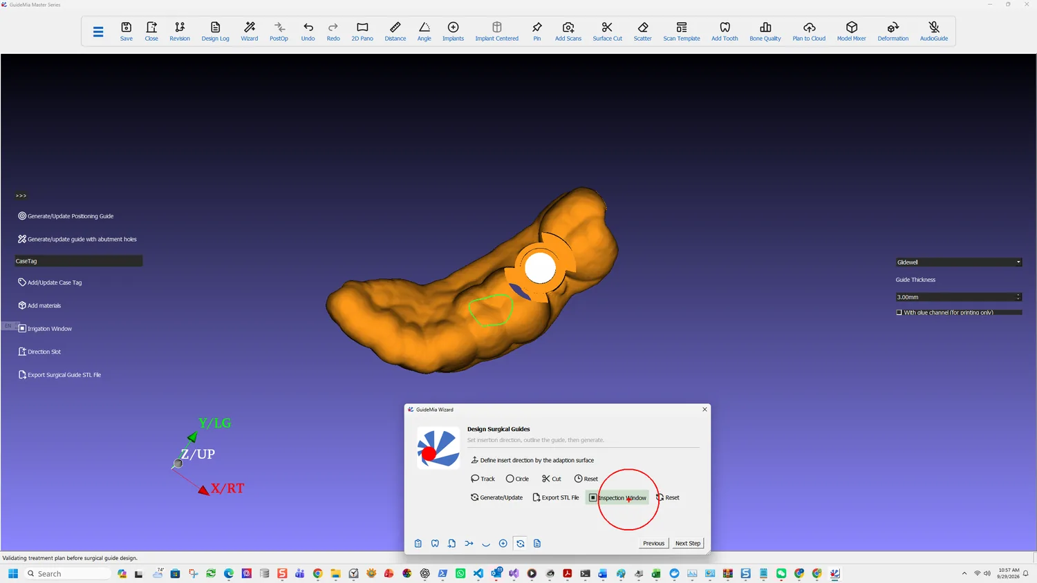
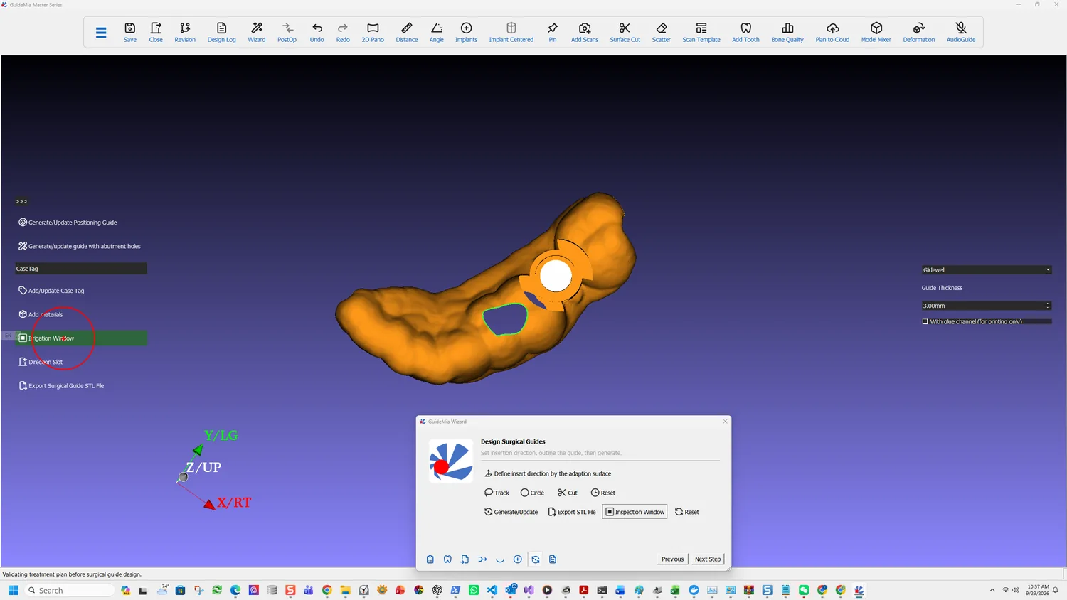
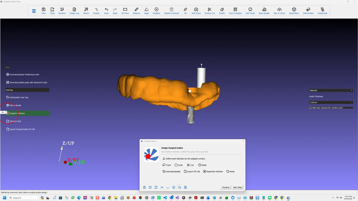
The guide exists. These two features are cut into it, and both are added the same way — click the model to place, then drag handles to shape.

They are easy to treat as optional. They are not: one is how the surgeon confirms the guide is properly seated, the other is how the bone survives the drilling.

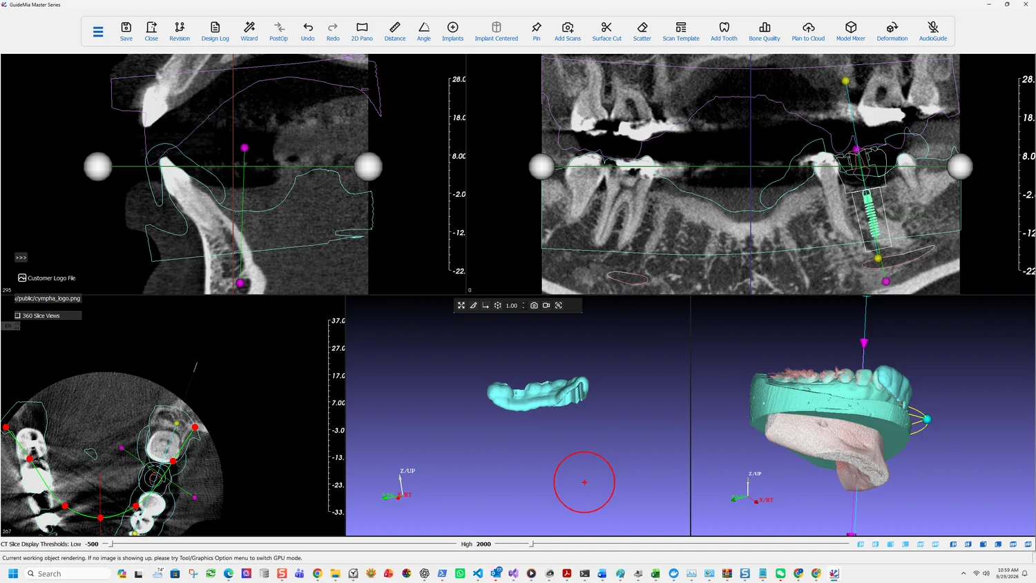
The generated guide, before windows are added

Inspection windows

Adding an inspection window

Add inspection window. Click on the model to add feature and manipulate it with handles.

An inspection window is an opening through the guide that lets the surgeon see the tissue underneath. Its purpose is confirmation: a guide that is not fully seated — rocking on a tooth, held off by soft tissue, sitting on debris — looks identical from outside to one that is. Through a window you can see the tooth surface it is supposed to be resting on.

Place them over the features that establish seating: the occlusal surfaces of the teeth the guide is supported by, particularly the ones furthest from the implant site, because those are where a rotation shows up first.

A second inspection window placed

Handles resize and reposition the window after it is placed, so the first click only has to be roughly right.

Irrigation windows

Adding an irrigation window

Add irrigation window. Click the model to place feature, and manipulate it by handles.

An irrigation window exists for heat. A guide covers the site it is drilling through, and a sleeve wraps the drill closely — which is exactly what stops coolant reaching the osteotomy. Bone is unforgiving about temperature, and overheating during preparation is a recognised cause of failed integration.

Place them adjacent to the sleeve, positioned so irrigant can reach the cutting site rather than run off the outside of the guide.

A further irrigation window

The two window types are separate features with separate buttons because they solve different problems and belong in different places — inspection over the support, irrigation beside the drilling.

What else goes on the guide

The sidebar carries the rest of the finishing work:

  • Direction Slot — a feature marking the insertion direction, so the guide can only be seated the way it was designed to be.
  • Add/Update Case Tag — text on the guide identifying the case. A printed guide with no marking is indistinguishable from any other printed guide, and they are not interchangeable.
  • Add materials — adds material where the guide needs bulk. This is what the Extraction option in implant placement triggers automatically, and it can be applied by hand where a span needs support the remaining teeth cannot give.
  • Generate/Update Positioning Guide and Generate/update guide with abutment holes — separate guide variants, generated from the same base.

Regenerating after a change

Windows survive a regeneration. If you return to planning, move a fixture, and come back to Generate/Update, the guide is rebuilt with the windows still in place. You do not replace them each time the plan moves — which is what makes it reasonable to add them before the plan is completely final.

More on this page

Post Processing in the workflow panel holds the operations applied to a generated guide beyond these.

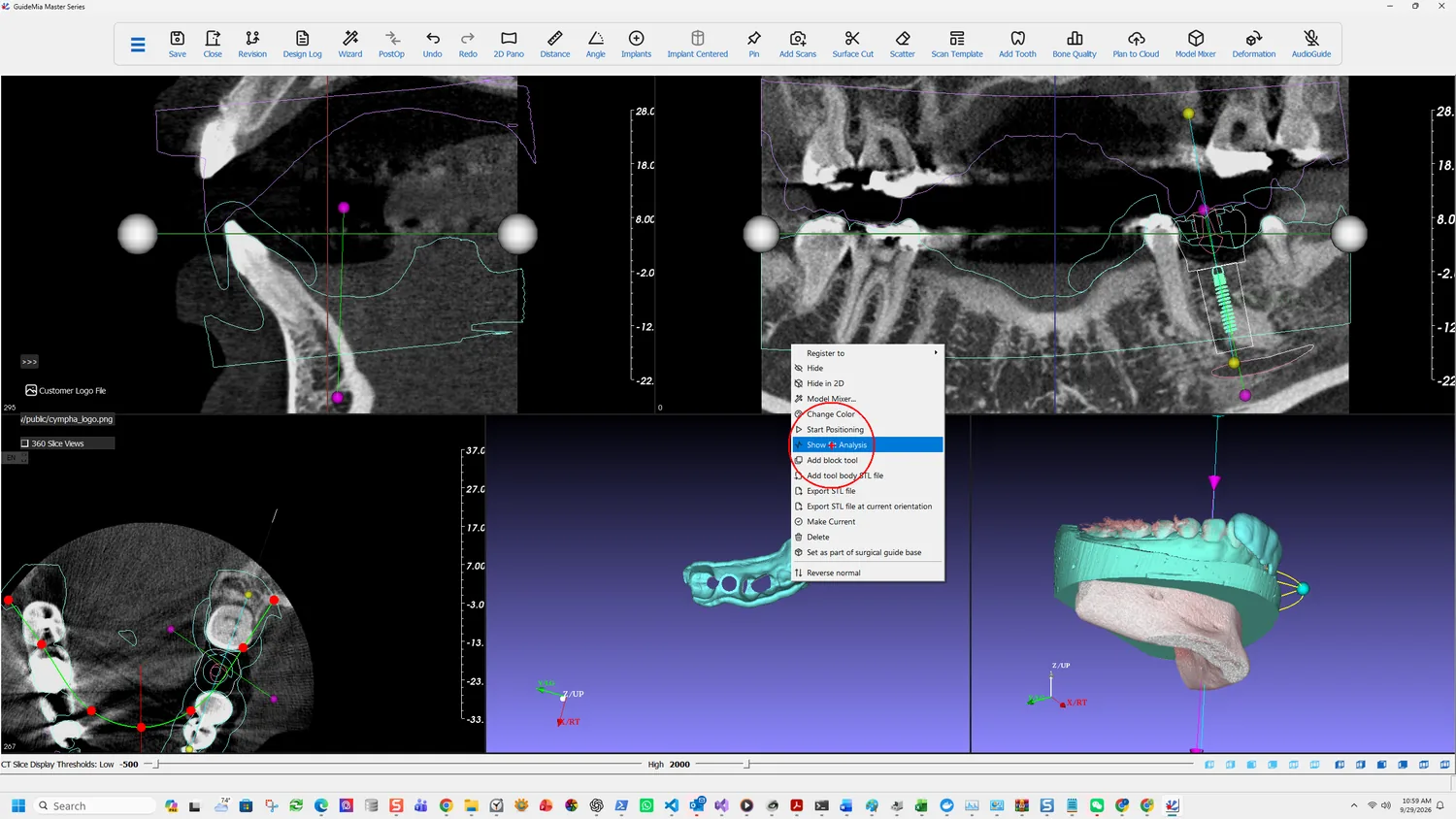
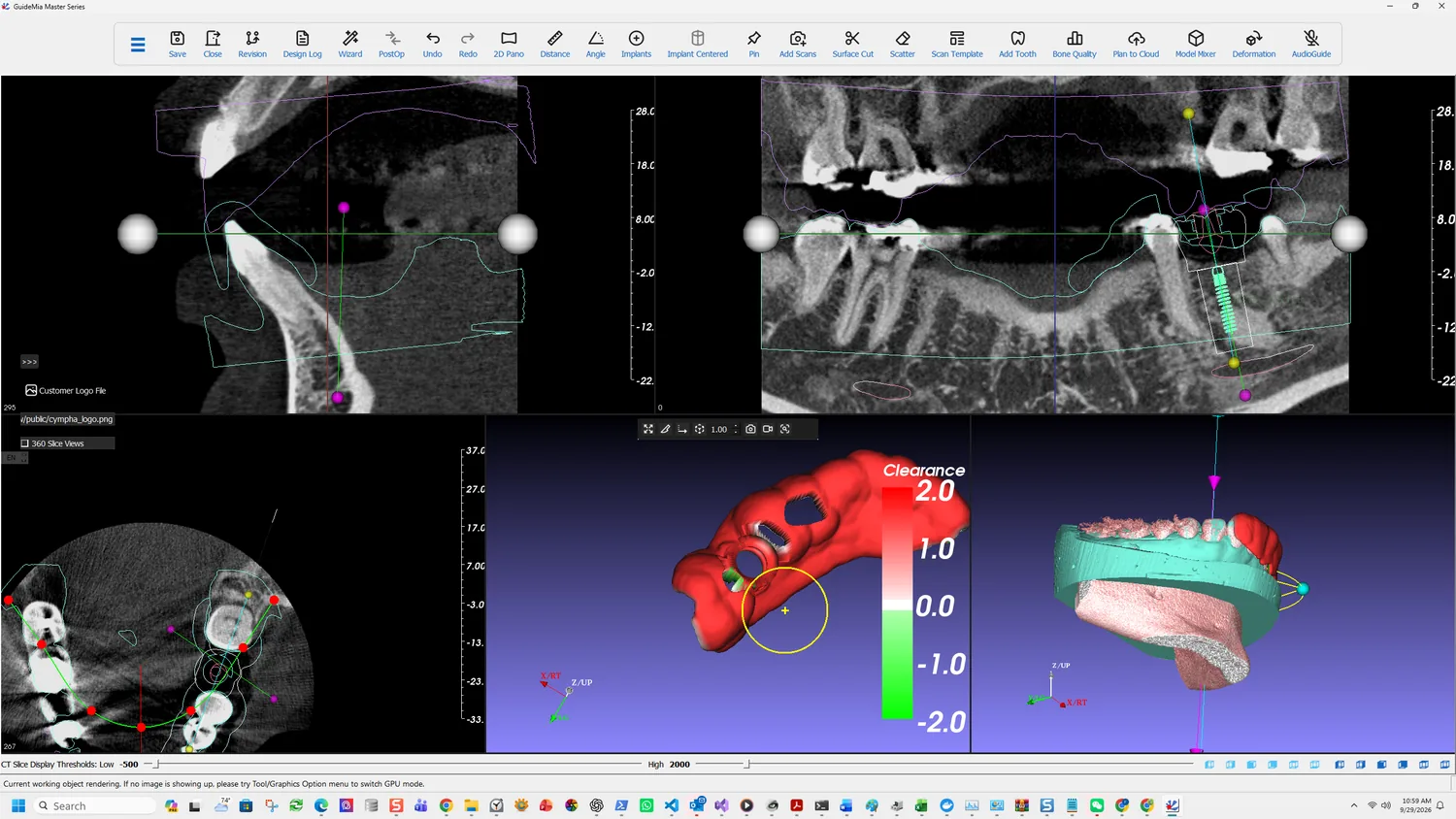
Right-clicking the guide in the assembly window reaches the object-level actions, which are the same for every object in the case: Register to, Hide and Hide in 2D, Model Mixer, Change Color, Start Positioning, Show Fit Analysis, Add block tool, Add tool body STL file, Export STL file and Export STL file at current orientation, Make Current, Set as part of surgical guide base, and Reverse normal.

Two of those matter here. Set as part of surgical guide base lets an additional object become part of what the guide is built from. And Export STL file at current orientation exports as you are looking at it rather than in the model's own coordinates, which is the difference between a file that drops onto a print bed correctly and one that has to be reoriented.

Part One · step 11 of 18

Export, save and report

The three things that leave the software — the guide for manufacture, the project for storage, and the report the surgery runs from.

Three different things leave the software at this point, and they go to three different places: the guide to whoever prints it, the project to your own storage, and the report to the surgery.

Export the guide

Export STL File

Export STL File writes the guide out for manufacture.

There is a second export worth knowing about, on the object's right-click menu: Export STL file at current orientation, alongside the ordinary Export STL file. The difference decides whether the file arrives on a print bed the right way up or has to be reoriented first — the plain export uses the model's own coordinates, the other uses how you are looking at it.

The toolbar also carries a general STL file export, and its status tip explains which object it acts on:

The system has two 3D windows. The left one is called working object window. The right one assembly window. In assembly window you can right click on any object and make it current using pop-up menu. It will then be displayed in the current object window. This export function will generate an STL file for the current object.

So current is a state you set, not a selection you make at export time. If the wrong object comes out, the fix is to make the right one current first.

Export DICOM file series is the other direction — it writes the volume of interest back out as DICOM, where the volume of interest is the area inside the rectangular boxes in the 2D windows.

Save the project

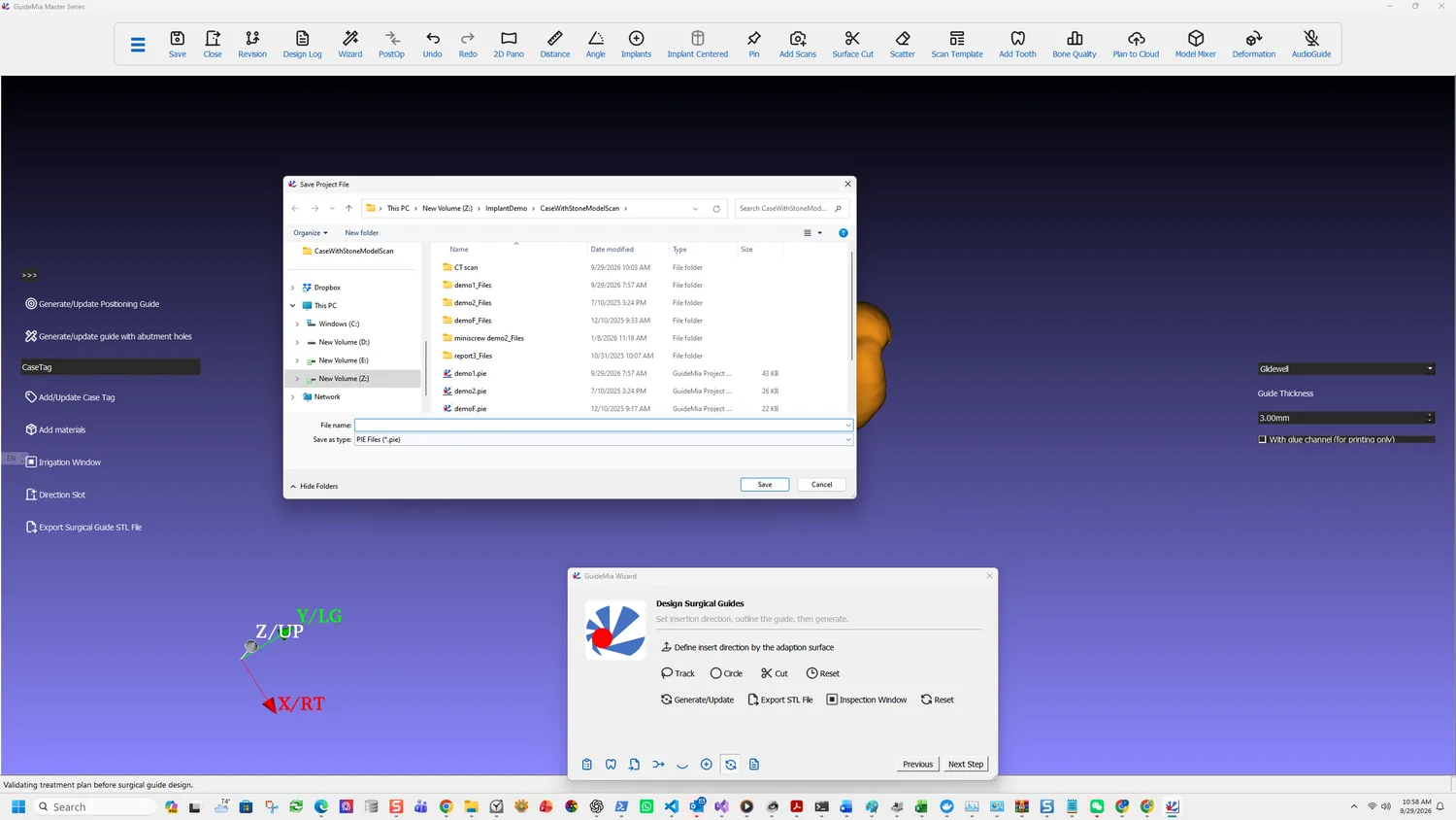
Saving the project file

The project file carries the case: the volume, the models, the plan, the guide and the revisions. Save writes it; Open takes it back.

For sending a case elsewhere there is Save for Transfer, which produces a package file rather than a project file. The distinction matters when a case has to reach someone who does not have your folder structure — Open accepts either.

Save Revision is separate and worth using deliberately. It stores the plan — the implants and their positions — under the case, so alternatives can be kept side by side and recalled with Switch to selected plan.

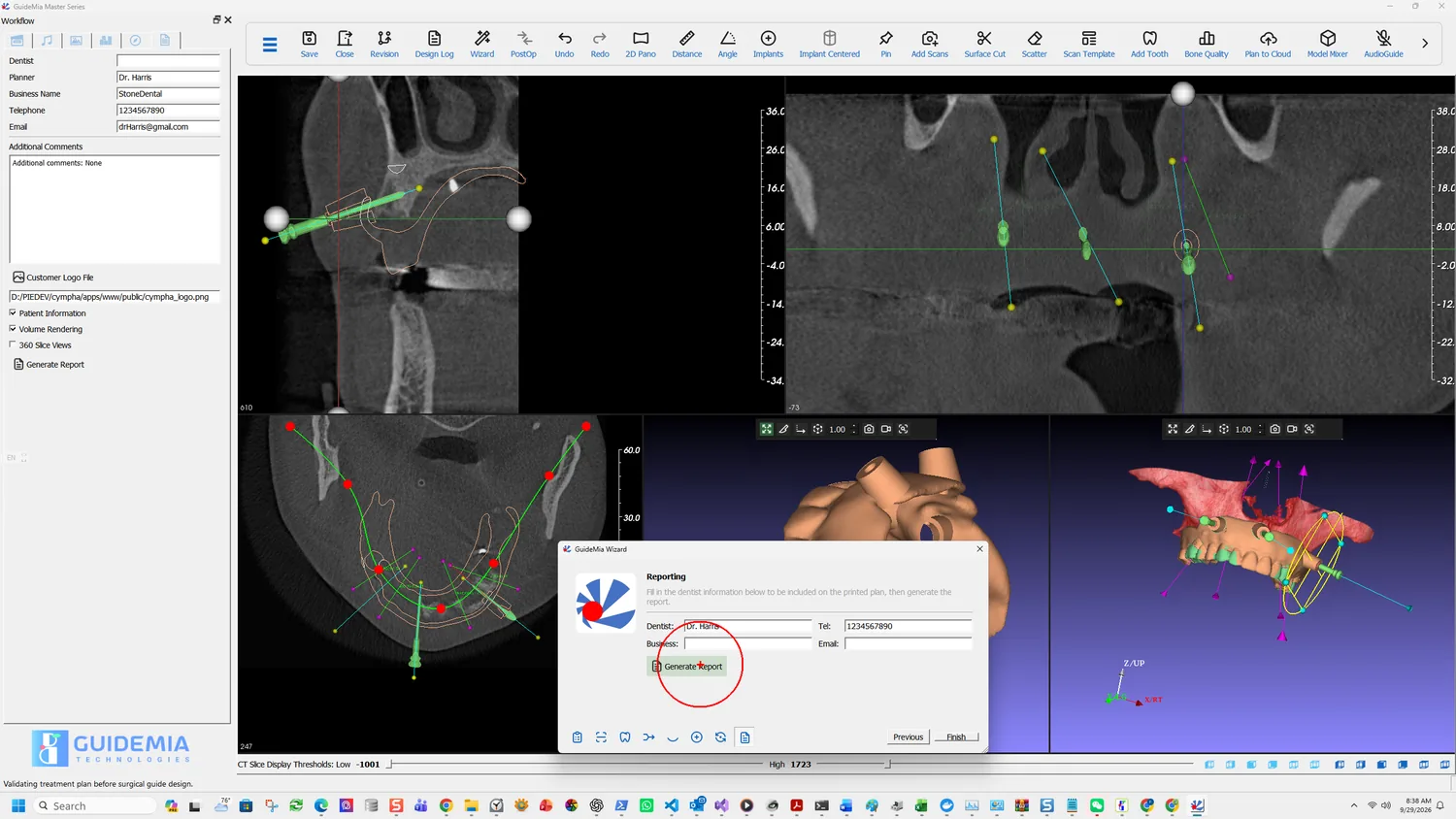
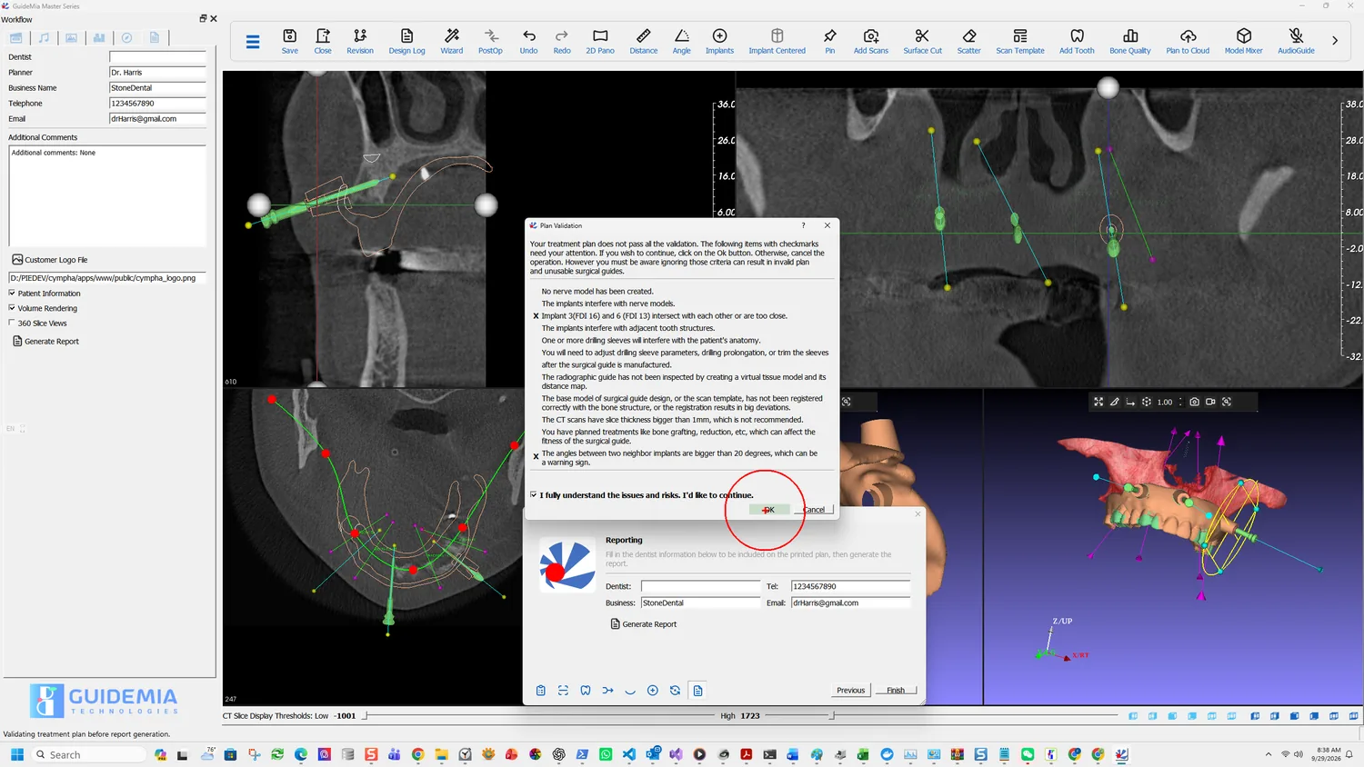
Generate the report

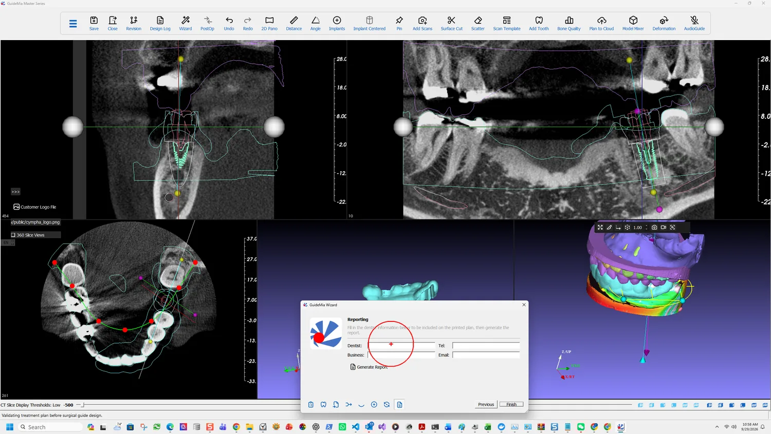
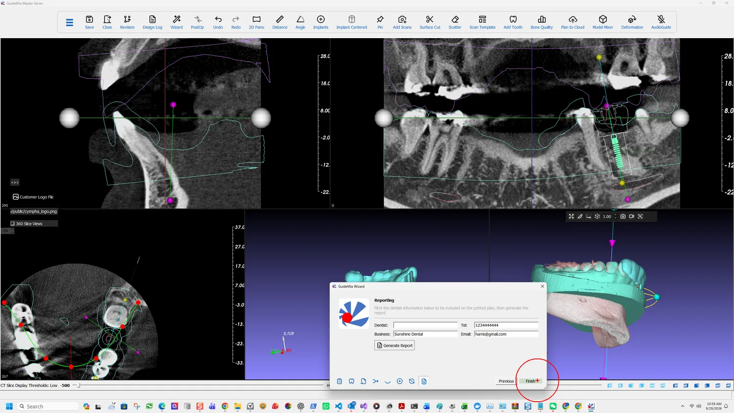
The Reporting page

The Wizard asks for the practitioner before it will produce anything: "Fill in the dentist information below to be included on the printed plan, then generate the report."

Dentist, Business, Tel and Email. These print on the plan, and they are how a question about it reaches the person who made it.

Two options sit in the sidebar, both easy to miss:

  • Customer Logo File — a logo to print on the report. A report that leaves the practice with a lab's or a clinic's own branding on it is a different document from one that does not.
  • 360 Slice Views — includes a full rotation of slice views rather than the standard set.

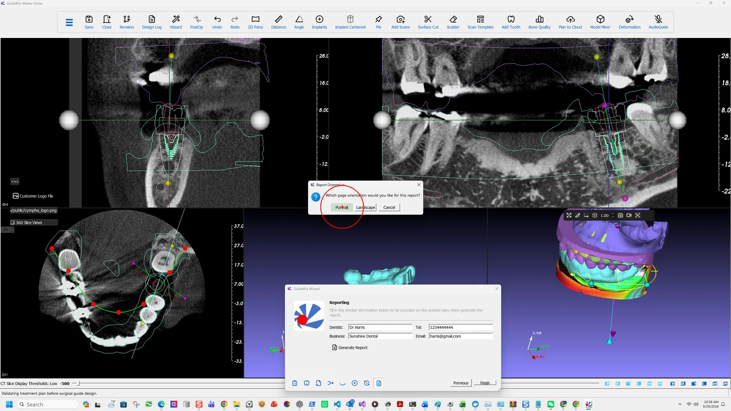
The orientation prompt, over the filled-in Reporting page

Generate Report then asks the one question the older releases left to the printer:

Which page orientation would you like for this report?

Portrait or Landscape. The report is largely tables, and landscape is what the release notes recommend — before this prompt existed, users had to remember to change the printer setting themselves.

The report generated

Both an HTML file and a PDF are produced, in matching languages.

What the report contains

Provider and patient — who planned the case and who it is for, with the case number and planning date.

Disclaimer and acknowledgement, with a signature line for the prescribing doctor. It states where responsibility sits: examination and diagnosis, and the determination of a medically sound treatment plan, are the prescribing doctor's. It is signed, not merely included.

Plan overview, and a panoramic view of the same plan.

Implant list — a row per fixture with the tooth number in both notations, implant diameter, apical diameter, implant length, total drilling length, make and part number.

Anchor pins, with a count.

Drilling instructions, headed by the surgical tool kit the guide was built for. This is where the plan meets the physical instruments, and it carries the rules that follow: a guide is designed for its matching kit by default, and a pilot-drill-only guide has holes matching the pilot drills defined by the implant platform or the kit, or 2 mm, whichever is smaller.

That last section is the one to read before surgery rather than during it. See the surgical kit for how those sleeves and drills are designed, and kit customisation if the kit is your own.

More on this page

Plan to Cloud on the toolbar sends the plan to Cympha rather than to a file, which is the route when the case is being reviewed by someone else rather than manufactured locally.

Design Log records what was done to the case. Revision manages the saved plans.

Part One · step 12 of 18

Fit analysis

The clearance map between the guide and the model it was designed from: what it measures, what it cannot tell you, and what to do about what it shows.

A guide can be geometrically correct and still not seat. Fit analysis is the check that separates the two, and it is the last thing worth doing before a case leaves the software.

The generated guide in the assembly window

What it actually measures

The manual is precise about this, and the precision matters for reading the result:

The idea is to calculate the deviations between the surgical guide and patient's anatomy, and visualize them. The "distance" is between a point on the surgical guide and the model that is used as the base for surgical guide design, such as a stone model for tissue-based guide or bone model for bone-level surgical guide.

So it compares the guide against the model it was designed from — in this case the registered intra-oral scan. That has a consequence worth stating plainly: fit analysis validates the geometry of the guide against the scan, not the scan against the patient. If the registration in step 5 was poor, fit analysis will show a beautiful result and the guide will still not seat.

Which is exactly why the manual lists it where it does — under improving the model registration. It is a visual tool for finding registration problems, and a clean map over an area you expected to be clean is evidence the registration held there.

Turning it on

Show Fit Analysis on the object context menu

Right-click the guide in the assembly window and choose Show Fit Analysis. It sits on the same object menu as Register to, Hide, Model Mixer, Change Color, Start Positioning, Make Current and the export entries — an object-level operation rather than a workflow step, which is why it does not appear in the Wizard.

Reading the map

The clearance map on the guide

The guide is recoloured and a Clearance scale bar appears beside it, running from +2.0 at the top through 0.0 in the middle to -2.0 at the bottom. The scale bar is the whole instrument — it defines how distance maps to colour, and the numbers are millimetres.

  • Green — negative clearance. The guide is closer to the base model than the nominal surface, or intersecting it. On a tissue-borne guide this is the side that will not seat: material has to go somewhere, and if it cannot, the guide rocks or sits high.
  • White — zero. Contact.
  • Red — positive clearance. A gap. Some is designed in; a large one over an area meant to provide support means that area is not providing it.

The case here reads red across the fitting surface, which is what a tooth-supported guide with designed relief looks like. What you are hunting for is local variation rather than an overall shade: a patch that differs from its surroundings is a feature of the scan or the design, and that is what to go and look at.

Rotating the guide through the map

Rotate through the whole fitting surface rather than judging one view. The areas that decide seating are the ones furthest from the implant site, because that is where a rotation shows up first — the same logic that governs where inspection windows go.

The underside, with sleeve holes and inspection window

The underside is the surface that meets the patient, so it is the one the analysis is really about. Here the sleeve hole and the inspection window are both visible in the map, and the margins around them are worth a look: a window cut close to a support area removes support from it.

What to do about what you find

A local green patch — the guide intersects the base model there. Check whether the scan has a defect at that spot; this is the same class of fault that makes Cut fail in guide design.

A large red area over an intended support — that region is not carrying the guide. Either extend the outline onto something that will, or accept it and rely on the remaining support, knowingly.

A map that disagrees with what you expected everywhere — suspect the registration rather than the guide, and go back to step 5.

The manual pairs fit analysis with one other remedy, and it is the one to reach for first: fine tuning. After registration you can slightly move or rotate the model so it better matches the patient anatomy. Fit analysis tells you which way.

And then the physical check

Fit analysis is a digital check against a digital model. It does not replace the one the Instructions For Use require:

The applicability of the surgical guides must be verified before the surgery... This includes trying the model onto diagnostic models, and on patient's anatomy. If a guide is found not fit properly on the patient's anatomy, or cannot be properly secured, it must not be used for the treatment.

Nor does the exported STL leave the software as a finished device — the guide must be finished with drilling sleeves before it is used. See intended use and safety.

More on this page

The system menu

The hamburger at the left of the toolbar opens the full system menu, and its status tip is the sentence to remember when a function in this guide is not where a figure shows it:

Open the full GuideMia menu with every Project / Edit / View / Diagnosis / Tools / Implant / Report / Update entry. Use this when a tool is not on the main toolbar.

That is the answer to most version differences. The toolbar and the icons change between releases; the menu carries everything regardless.

Part One · step 13 of 18

Accuracy and planning error

Where the deviation in a finished implant position comes from, which parts of it you control, and how plan error simulation tells you whether a plan tolerates the rest.

Every guided case ends up somewhere slightly different from where it was planned. This chapter is about where that difference comes from, how much of it you control, and what the software can tell you about tolerating it.

It is background rather than a step. Nothing here is on the Wizard.

The three places error comes from

The error in a finished implant position accumulates from three sources, and they behave differently:

Image processing errors — registration error and segmentation error. Behind both sits the actual accuracy of the DICOM files from the scanner.

Manufacturing errors in the guide itself:

  • guide dimension errors
  • hole position linear errors
  • hole position angular errors
  • linear deformation of the guide
  • angular deformation of the guide

Positioning error at treatment time — how accurately the guide seats, and how accurately the implant is placed relative to the planned position and orientation.

The division that matters:

The image processing errors will affect the design of surgical guides, and the manufacturing errors and positioning errors will affect the deployment of treatment plans.

In other words, the first group is yours to fix in the software. The second and third are decided by your lab and your hands, and the software's role there is to tell you whether the plan tolerates them.

What the measurements are worth

The measurement features — dimension and angle — are guaranteed to errors smaller than 0.01 mm or 0.05 degree.

That figure describes the software's arithmetic and nothing else:

All the measurements are subject to the accuracy of the input datasets. Please refer to the specs of your CT and optical scanners.

A plan is no more accurate than the scan it was built from. The 0.01 mm is not a claim about your case.

Reducing the error you control

Slice thickness

This is the single largest lever, and it is pulled before the patient leaves the scanner.

Because of this, we do not recommend planning cases with slice thickness bigger than 1mm. Thickness of 0.25mm or lower is preferred.

The scanning protocols ask for 0.2-0.5 mm for this reason. A case scanned at 1 mm is not merely lower resolution — it is outside what the manufacturer recommends planning on.

Calibrate the devices

If you make your own guides, calibration is not optional:

Device calibration is critical to have a satisfactory treatment plan and outcome.

That covers the CT or CBCT scanner, and whichever machine produces the guide — a CNC mill, a 3D printer, or an SLA machine. Calibrate regularly, and ask the operators for the equipment's actual scanning and manufacturing errors. Those numbers are the inputs to error simulation below.

Prefer an optical scan to a radiographic guide

This is the manufacturer's own recommendation, stated plainly:

If the users prepare their cases with optical scan of stone models, or intra-oral scans, the accuracy is a very minor concern. Most of the time the surgical guide design based on an optical scan will fit on the patient anatomy very well. Therefore, optical scan is actually recommended over radiographic guide.

Which is why Part One follows the optical route. The radiographic guide protocol exists for the cases the optical route cannot serve — chiefly metal artefact near the implant sites — rather than as an equal alternative.

If you do use a radiographic guide, model it by measurement

It is strongly recommended that users use the segmentation threshold filter to create a radiographic model from its CT scan. When adjusting the threshold, measure the digital model displayed on the screen and the physical model to make sure the threshold is set such that the reconstructed model replicates the size and thickness of the physical model.

That is a calibration step, not a visual judgement: put callipers on the physical guide, measure the same feature on screen, and set the threshold so they agree. A threshold chosen by eye produces a guide of the wrong thickness, and the error carries straight through to the fit.

Improve the registration

Since the guide is designed from the registered model, the registration between that model and the patient scan is decisive for the guide's accuracy. Two tools address it:

  • Fine tuning. After registration, move or rotate the model slightly so it better matches the anatomy. Described in step 5.
  • Fit analysis. Visualises the deviation between the guide and its base model, which is how you find out whether the registration held. Step 12.

Plan error simulation

The remaining error — manufacturing and positioning — cannot be removed. What the software offers instead is a way to find out whether your plan survives it.

Plan Error Simulation lives on the Treatment Planning page. It applies deviations to the implant positions and updates the display continuously, so you watch the plan move through its error envelope rather than reading a number.

How a deviation is described

An error source is first translated into a deviation of implant position and orientation. A linear error is a shift of the coordinates, (dx, dy, dz). An angular error is a deviation of the orientation — and since rotation about the implant's own axis does not really change its position, only the rotations about X and Y are considered, as angle_x and angle_y.

So one deviation has five components: (dx, dy, dz, angle_x, angle_y). Those five define what the manual calls the error space.

How the simulation runs

You designate the error factors and their distributions in the dialog. Examples of what to enter: errors of stone models, manufacturing errors and deformation of radiographic guides, errors in radiographic guide placement, errors of CT image processing. Each factor is given a maximum deviation and a statistical distribution.

The software then generates a series of values for each component — from −maximum through zero to +maximum in steps — and combines them. For each combination it moves the implant model: it stores the apex coordinates, translates the apex to the origin, rotates about X by angle_x, rotates about Y by angle_y, and translates back by (x+dx, y+dy, z+dz).

The display updates through the whole series, in both the 3D and the 2D views, with bone and implants shown at minimum. The result is real-time visual feedback: you see where the fixture goes at the extremes of what your equipment and technique can produce.

What to do with it

Pair it with Bone Quality visualisation, which is what the design intends — you are asking whether the fixture is still in sound bone, and still clear of the canal, at the far edge of the error envelope.

If the answer is no, the plan is not wrong so much as intolerant, and the options are the ordinary ones: move the fixture to somewhere with more margin, choose a different size, or reduce the error by scanning thinner and calibrating the printer.

This is the honest version of the check that the four questions in step 8 ask by eye.

The limit of all of it

None of the above makes a plan safe. The Instructions For Use are direct about where the analysis stops:

One-hundred percent success cannot be guaranteed no matter a treatment is planned with software or physical models.

And the specific trap this chapter is closest to is a measurement one:

Failure to recognize the difference between the actual length of the drill and radiographic measurements can result in permanent injury to the nerves or other vital structures by drilling beyond the depth intended.

Drill length reference lines on some systems measure longer than the stated implant length. The software plans in the numbers it is given; the surgeon is expected to know their own kit's measurement system and to keep a suitable safety margin from teeth and vital structures.

Part Two — the full-arch case

A maxillary full arch on a radiographic guide: four fixtures, three anchor pins and a tissue/tooth-borne guide. Part One is the prerequisite rather than an alternative — these chapters cover only what a full arch adds.

Part Two · step 14 of 18

Starting a full-arch case

Why a full arch is usually a radiographic-guide case, loading the scan template and setting its threshold by measurement, and segmenting an edentulous ridge without the AI engine.

Part One is the prerequisite for this part, not an alternative to it. The thirteen steps are the same and are not repeated here; what follows is the work a full arch needs and a single unit does not.

The case this part follows is a maxillary full arch on a radiographic guide — four fixtures, three anchor pins, a tissue/tooth-borne guide, planned against the Camlog kit. It begins differently from Part One at the second dialog.

Starting the case

Why this case is not an optical scan case

A full arch is very often the case the optical protocols cannot serve, and the software says why on the button itself:

Load Radiographic Guide CBCT scan or optical scan. Radiographic guides are for two categories of cases. First, for fully edentulous case, you use radiographic guides to represent the gum surface and the possible tooth arrangements. Secondly, for some partially edentulous cases, when there isn't enough natural tooth area for registering the CBCT data and a model scan, for example, a patient may have a long bridge from metal or ceramics, which can cause a lot of scatters in the CT scan. For this kind of situations, using radiographic guides can help get clear gingiva the tooth surfaces.

Both halves of that describe a full arch. An edentulous ridge has no tooth surfaces to scan and no tooth arrangement to plan against, so the guide has to carry both. And where teeth remain, they are often the heavily restored ones that scatter the CT.

So Part Two takes the dual scan with radiographic guide protocol from step 2, and the guide itself was made before anyone opened the software — to the checklist in before you start: 2.5-4 mm thick, no metal, 6-8 spherical markers of 1.5-2.5 mm, half lingual and half buccal, deliberately unevenly distributed.

Declining the AI

The AI segmentation prompt, declined

This case answers No at the opening prompt, which is worth understanding rather than copying. AI segmentation is built around teeth and roots; on a fully edentulous maxilla there are none to find, and the bone here is thin-walled and pneumatised. Declining it means segmentation is done in full by hand, with thresholds, region of interest and seed points.

You can still press AI Segmentation on the segmentation page afterwards. What you lose by answering No is only the head start, not the option.

Loading the radiographic guide

The Radiographic Guide page, with the scan template threshold

The Wizard's page is short: "Load the radiographic-guide CBCT scan and adjust its segmentation threshold below."

Load radiographic guide CT takes the second DICOM series — the scan of the guide alone, not the patient wearing it.

Scan Template Segmentation → Threshold is the control that decides how accurate this case can be, and it reads −512 here. It is not a cosmetic setting. The manual is specific about how to choose it:

When adjusting the threshold, measure the digital model displayed on the screen and the physical model to make sure the threshold is set such that the reconstructed model replicate the size and thickness of the physical model.

Put callipers on the physical guide, measure the same feature on screen, and move the threshold until they agree. A threshold set by eye produces a guide model of the wrong thickness, and that error carries all the way through to the fit of the printed guide. See accuracy.

The sidebar carries the other reference models this page can take: Stone model or intra-oral scan, Denture design, and Add face picture or smile design picture.

Segmenting the bone by hand

Setting the bone threshold

With AI declined, the three manual inputs from step 3 all matter, in order: thresholds first, then the region of interest boxes, then seed points.

Adding a seed point

Add the seed points. As mentioned in the lower threshold instruction, this tool is to select different areas in the CT data.

One seed is usually enough. Put it in solid bone, never in the black area — those voxels have already been discarded by the threshold, so a seed there selects nothing.

Tissue peeling

Tissue Peeling at 1.50 mm matters more here than on a dentate case:

Sometimes patients' bone dentistry is low, it is almost impossible to create a good solid model of the bone structure for 3D printing or bone level surgical guide design. The parameter next to this button is roughly the size of the holes you want to fill in. Normally it is from 1 to 3mm or slightly bigger. Smaller values don't do much.

An atrophic edentulous ridge is exactly the low-density case that sentence describes. Without peeling, the segmented surface comes out perforated.

The segmented maxilla

What carries over unchanged

Everything else in the preparation stage is Part One as written: registration of the scan template against the bone, additional scans, and the views you judge on. The one difference is what you are registering — a radiographic guide rather than an intra-oral scan — and the markers you pair are the radiographic markers built into it rather than cusp tips.

More on this page

The full Load Case Data page carries the impression and denture routes described in step 1. For a full-arch case the Denture design entry is the one worth knowing: it loads a digital denture design, which can be registered against the radiographic guide or against the gingiva model alone, and GuideMia can then add abutment holes to it or generate a prosthesis guide so occlusion and guide position can be checked before any drilling.

Part Two · step 15 of 18

Implants along the arch

Copy Implant, which replicates a fixture's specification and angulation onto the next tooth, the safety zone across several fixtures, and the twenty-degree rule between neighbours.

One fixture is a placement decision. Four are a placement decision plus a relationship — to each other, and to the guide that has to clear all of them at once. This chapter is about the second part.

Browsing the implant library

The first one is a Part One problem

Pick the tooth, choose the fixture, judge it on all three planes: exactly step 7. This case uses CAMLOG SCREW-LINE Promote, 3.80 mm diameter, 3.54 mm apical, 11.00 mm long, against the Camlog surgical kit, which the software matched to the implant automatically.

The first fixture placed

Spend the time here. Everything after it is a copy of this decision, so an angulation that is slightly wrong gets replicated rather than corrected.

Judging it on the slices

Two controls on the full Place Implants panel earn their place on a full arch:

  • Show Safety Zone, set to 1.50 mm here, draws the clearance envelope the manual defines as "an area in the 3D space surrounding an implant. There should be no interference with adjacent tooth roots, implants, nerves, sinuses, etc." On a single unit you are watching one envelope. Across an arch you are watching them not touch each other.
  • Show sleeves, because sleeves are considerably larger than fixtures. Two implants that clear each other comfortably can have sleeves that collide, and the guide is built to the sleeves.

Copying it down the arch

Copy Implant on the right-click menu

Right-click a placed implant in any 2D view and the object menu offers Edit, Delete, Edit implant number, Copy Implant and Change Color.

Copy Implant is the full-arch tool. It duplicates the current fixture — the same make, model and size, and the same orientation — onto another tooth, at a position the software estimates for that site.

The Tooth Number dialog

It asks which tooth, and the number it offers is the next one along: the source here is 3 (16) and the dialog opens on 4 (15). Accept it or pick any other.

Two behaviours worth knowing before you rely on it:

It refuses to overwrite. If an implant already exists at the number you choose, you get "Implant exists." and nothing happens. To move an implant to a different number instead, use Edit implant number, which renumbers it in place rather than creating a second one.

The position is an estimate, the angulation is a copy. The software works out where that tooth site is and puts the fixture there; the direction comes straight from the implant you copied. So the copy arrives plausible rather than correct, and it still has to be judged on all three planes like any other.

The copied fixture, adjusted

What this saves is not the placement — it is the specification. You choose the implant system, diameter, length, kit, sleeve and depth once, and every subsequent site inherits them without going back through the library.

Working along the arch

Making them parallel, and the number that decides

Make dental implants parallel sits in the sidebar of the Place Implants page. It aligns multiple fixtures, and it is meaningless on a single unit.

Parallelism is not only a prosthetic preference. It is a validation criterion, and the software states the threshold:

The angles between two neighbor implants are bigger than 20 degrees, which can be a warning sign.

Twenty degrees between neighbours. That is checked before guide design and reported in the plan validation dialog covered in the next chapter but one. It is worth knowing the figure while you are still placing, because correcting divergence now costs a drag and correcting it later costs a regenerated guide.

A related tool lives on the coronal view's context menu: making an abutment parallel to its neighbour rather than the fixture, which is the right handle when the restoration drives the case.

Depth, across several fixtures

All four fixtures placed

Automatic drilling depth control, with a Depth Control Option in millimetres, applies a consistent depth rule rather than leaving each site to be set by hand. Depth by Drill Length does the same from the other end — "You can set the total drill length as you like" — and reads 23.50 mm here, against the 14.50 mm the single-unit case used.

That difference is the whole argument for setting it deliberately. The drill length is what reaches the surgical kit and the report, and the Instructions For Use are blunt about the consequence of getting it wrong:

Failure to recognize the difference between the actual length of the drill and radiographic measurements can result in permanent injury to the nerves or other vital structures by drilling beyond the depth intended.

More on this page

Previous / Next Implant step between fixtures, which is how you review an arch rather than clicking each one in the 3D view.

The panel also carries System Library and User Library side by side — the shipped catalogue and the one you added yourself — plus the abutment attached to the current implant, here K2202.3815_Rev_00.stl.

Force fully guided design even with universal kit decides what happens when a case falls back to the GuideMia universal kit: without it, the guide is pilot-only.

Three workflow pages beside this one exist for cases a single unit rarely raises and a full arch often does: Anchor Pins or Screws (next chapter), Bone Reduction or Combined Guide Splitting, and Bone/Sinus Graft. Plan Error Simulation is on the same panel, and an arch is where it earns its keep — see accuracy.

Part Two · step 16 of 18

The virtual tissue model

The step that exists only on a radiographic-guide case: reconstructing the tissue surface from the scan template, and reading the tissue-thickness map the software insists you look at.

This step exists only on a radiographic-guide case, and it is easy to skip because nothing obviously breaks if you do. The software disagrees: skipping it raises a plan validation warning at guide design.

Opening the full workflow panel

It is not on the Wizard. >>> opens the full workflow panel — "Turn on the full workflow panel and access more functions" — and Virtual Tissue Model is a page in it, between Model Registration and Nerve Channel Definition.

What a virtual tissue model is

The manual defines it by analogy:

A geometric model generated based on CT scan dataset to simulate the actual soft tissues and tooth surfaces. Since this virtual model is similar to a stone model that typically includes soft tissue and tooth surfaces, the model is called virtual tissue model.

On a case planned from an intra-oral scan you already have that surface — the scan is it. On a radiographic-guide case you do not. What you have is a model of the guide, and the guide is an object that was made to sit on the tissue, not a record of the tissue itself. The virtual tissue model is how the software reconstructs the one from the other.

Setting the insertion direction first

The Virtual Tissue Model page

The page states the prerequisite in its own words:

In order to generate virtual tissue model from the scan template, [it is] necessary to set the insertion orientation. Rotate the model in [the] window so that the side touching the patient's anatomy is visible, then check the following item.

So the input is the camera again, exactly as in guide design. Turn the scan template over until you are looking at its fitting surface, then tick The insertion direction is good.

Show me the scan template displays it, which is what you rotate.

Generate virtual tissue surface then builds the model.

The distance map is the point

The tissue thickness map over the palate

Along with the surface comes the thing this step is really for:

Distance map between scan template and bone structure. The distances are visualized by colors.

Tick Show the distance map and the model is recoloured, with a scale labelled Tissue thickness running from 10.0 at the top through 3.5 to 0.2, and into negative values at the bottom.

Read it as the soft tissue the guide is sitting on:

  • Warm colours — thick tissue. The guide is bearing on several millimetres of mucosa. Mucosa is compressible, so a guide seated on it can be pressed further home than the plan assumed, and the drilling depth follows the guide.
  • Green through pale — moderate. The working range.
  • Towards zero and below — the guide is close to, or through, the bone surface. Negative tissue thickness means the scan template and the bone model intersect, which is either a registration error or a guide that does not actually fit the patient the way the scan suggests.

This is the same idea as fit analysis applied one step earlier: there you compare the finished guide against its base model, here you compare the base model against the bone.

Why the software insists

Skip this and guide design raises it, in the plan validation dialog:

The radiographic guide has not been inspected by creating a virtual tissue model and its distance map!

That wording is worth reading closely. The software does not call the model an output. It calls generating it an inspection — the step is there so that somebody looks at how the guide meets the tissue before a surgical guide is built on top of it.

On a fully edentulous arch that matters more than anywhere else in the software. There are no teeth to seat on, so the entire fit is mucosal, and mucosal thickness is the one variable that moves between the scan and the day of surgery.

More on this page

The same workflow panel carries Nerve Channel Definition immediately below. On a maxillary case the canal is not the concern the sinus is, but the page is the same one, and the plan validation will report "No nerve model has been created" whether or not a nerve was relevant to your case — see the next chapter for how to read a warning that does not apply.

Part Two · step 17 of 18

Anchor pins

What holds a guide that has no teeth to seat on: placing pins, the colour change that is the only interference warning, and what the guide and the report do with them.

A tooth-supported guide seats on teeth and stays where it is put. A full-arch guide on an edentulous ridge has nothing to hold it: it sits on compressible mucosa, it is long enough to rock, and every drill that passes through it pushes it. Anchor pins are what fix it to the bone.

This case uses three.

Adding an anchor pin

Placing one

Pin is on the Wizard's Place Implants page and on the toolbar, and the mechanic is the same as placing a fixture:

Add an anchor pin by clicking the desired site in any of the image windows, and then you can move and rotate the anchor pin. When the pin is too close to implants or other pins, it will turn red.

Click a site in any window — 2D or 3D — then move and rotate it as needed.

The red warning is the whole safety mechanism of this step, and it is worth stating plainly because it is passive: nothing stops you, nothing warns in words. A pin too close to an implant or to another pin simply changes colour. If you are placing three pins around four fixtures while rotating the view, that is easy to miss.

The first pin in place

Where they go

The pins have two jobs and they pull in slightly different directions.

Hold the guide down. That argues for spreading them as widely as the guide allows — anterior and both posterior ends — because a guide pinned only at the front rotates about that point, and rotation at the front is displacement at the back, where the longest fixtures usually are.

Stay out of the way. Each pin needs bone to engage, clearance from every fixture and every sleeve, and a path that the surgeon can actually reach with the guide seated.

A pin placed posteriorly

The parameters are on the right of the Place Implants page, and they are set before you place rather than after:

  • Anchor Pin Diameter — 1.50 mm here
  • Anchor Pin Length — 20.00 mm
  • Update current anchor pin applies a change to the pin you have selected

Twenty millimetres is long, and deliberately so: a pin has to pass through the guide, through the mucosa, and far enough into bone to resist the drilling.

All three pins, with the four fixtures

What the guide does with them

The pins are not an annotation. Generating the surgical guide puts a hole through it for each one, dimensioned to the pin diameter you set, which is why the parameters have to be right before the guide is built rather than after.

They also reach the report. The plan carries an Anchor pins section with a count, so the surgery knows how many to have ready and at what size — see export, save and report.

The sequence at surgery

Worth being explicit about, because the order is not obvious from the software: the guide is seated, the pins are placed through it to fix it, and only then is anything drilled. A pin placed after drilling has begun is fixing a guide that has already moved.

More on this page

Anchor Pins or Screws is a page of its own on the workflow panel, beyond the Pin button the Wizard exposes. Screws are the alternative fixation where a pin will not serve.

The right-hand panel on the same page also carries the sleeve dimensions the guide will be built to — Sleeve Thickness 0.68 mm, Sleeve Length 5.25 mm and Sleeve Flange Thickness 0.90 mm in this case, following the Camlog kit. Those are the numbers customising a kit sets for a kit of your own.

Part Two · step 18 of 18

The full-arch guide and report

The plan validation gate and every criterion it checks, the guide parameters a long span needs, splitting, and the report a four-fixture case produces.

Guide design validates the plan before it builds anything. On a single unit that check usually passes silently. On a full arch it usually does not, and the dialog it raises is the most useful screen in the software.

The plan validation gate

The Plan Validation dialog

Your treatment plan does not pass all the validation. The following items with checkmarks need your attention. If you wish to continue, click on the Ok button. Otherwise, cancel the operation. However you must be aware ignoring those criteria can result in invalid plan and unusable surgical guides.

Every criterion the software checks is listed, and the ones that failed carry an X. The full list:

CriterionWhat it means
No nerve model has been createdNothing was traced, so no clearance check was possible
The implants interfere with nerve modelsA fixture is in the canal
Two implants intersect or are too closeNamed by tooth number, in both notations
The implants interfere with adjacent tooth structuresA fixture is into a neighbouring root
One or more drilling sleeves will interfere with the patient's anatomyThe sleeve, not the fixture — a separate check
Sleeve parameters, prolongation or trimming will need adjusting after manufactureA consequence of the previous one
The radiographic guide has not been inspected by creating a virtual tissue model and its distance mapThe previous chapter was skipped
The base model or scan template is not registered correctly, or the registration has big deviationsThe registration itself is in doubt
The CT scans have slice thickness bigger than 1 mmOutside what the manufacturer recommends planning on
Treatments like bone grafting or reduction are planned, which can affect the fitness of the guideThe anatomy will not be what the guide was built to
The angles between two neighbour implants are bigger than 20 degreesThe parallelism threshold from the arch chapter

In this case two are marked:

X Implant 3(FDI 16) and 6 (FDI 13) intersect with each other or are too close.

X The angles between two neighbor implants are bigger than 20 degrees, which can be a warning sign.

Both are full-arch failures by nature — neither can occur with one fixture. Note that the first names the implants in both notations, so there is no ambiguity about which two to go back and look at.

Overriding it

The dialog will not let you past by accident. OK is gated behind a checkbox you have to tick:

I fully understand the issues and risks. I'd like to continue.

That is a deliberate design and it deserves a deliberate response. Two of these criteria are routinely ticked on cases that are perfectly sound — a maxillary case has no mandibular canal to trace, so "No nerve model has been created" is expected — and two of them are almost never acceptable, namely implants intersecting and a registration in doubt.

The distinction is yours to make. What the software guarantees is that you made it knowingly.

Designing the guide

Setting the insertion direction

From here the sequence is step 9: Define insert direction by the adaption surface takes the direction from the view, then the base is outlined and cut, then generate.

The parameters on the full Surgical Guide Design page are where a full arch differs, and three of them do not appear in a simple case:

Define guide type reads Tissue/tooth-borne here rather than a purely tooth-level guide. That follows from the case: there are not enough teeth to carry it.

Undercuts, with an angle — 12 deg. A long span across an arch crosses ridge form that a rigid guide cannot be pulled off, and this is the relief that lets it seat and release. A single unit spanning two teeth rarely needs it.

Contacting surface compensation — 0.0250 mm. The allowance between the guide's fitting surface and the model it was built from, which is the manufacturing tolerance rather than a design preference.

Alongside them: the guide style, Cylindrical here rather than Rectangular, with Radius Delta 4 mm and Sleeve Housing Thickness 2 mm, and Guide Thickness 3.00 mm.

Generate/Update

Generate/Update builds it, and on a case with several guide types it builds them all at once:

In case of bone reduction guides, plateau guides and combined guides, this will generate all guides together.

The generated full-arch guide, with fixtures and pins

The result carries everything planned: four sleeve holes and three pin holes through one body.

Splitting, when it will not print or seat

Split Guides for Full Arch is its own entry on the workflow panel, below Master Model. A full-arch guide can be too long for the printer, or too rigid to seat over an arch with any undercut left in it; splitting divides it into sections that can be printed and placed.

The recorded case does not split — it prints in one piece. Reach for it when the span or the printer says otherwise, and note that the pins become more important, not less, once the guide is in pieces.

The report

The Reporting page

Identical to step 11: dentist details, the Customer Logo File and 360 Slice Views options, then Generate Report and a Portrait or Landscape prompt.

What changes is the content. A full-arch report carries a row per fixture in the implant list — tooth number in both notations, diameters, lengths, make and part number — and an Anchor pins section with the count. Both are things the surgery reads rather than the planner.

The report generated

The Drilling instructions, headed by the surgical tool kit, are the section to read before surgery rather than during it. With four fixtures there are four sequences, and they are not necessarily the same.

Exporting everything at once

Export all models as one file

The assembly window's right-click menu carries Export all models as one file, which is the export a full-arch case usually wants: the guide, the fixtures, the pins and the scan template written together rather than one object at a time through Make Current.

For sending the case rather than the geometry, Save for Transfer produces a package file — see export, save and report.

Before it goes to the lab

Nothing about a full arch changes what the Instructions For Use require, and two of them bite harder here:

The surgical guide model created by GuideMia is not intended for direct clinical use. The users must finish the surgical guide with additional drilling sleeves.

Seven holes to sleeve and pin on this guide, not one.

If a guide is found not fit properly on the patient's anatomy, or cannot be properly secured, it must not be used for the treatment.

"Cannot be properly secured" is the anchor-pin clause. A full-arch guide that will not pin is not a guide.

Part Three — reference

Two set-up tasks rather than case steps. Each is done once — when your implant system or your surgical kit is not one of the shipped ones — and then holds for every case after.

Part Three · reference

Expanding the implant library

Adding an implant system GuideMia does not ship: where the files go, the coordinate system every implant and abutment STL has to be in, and the catalogue format support accepts.

GuideMia ships with a long list of manufacturers, and Browse in implant placement reaches all of them. When the implant you use is not among them, you add it yourself — and once it is in, it behaves exactly like a shipped one.

This page covers both routes: adding implants with their geometry, and adding them as parameters only.

Two kinds of entry

Parameters only. An implant defined by its dimensions — platform diameter, apical diameter, catalog length, total length. The software plans with it, sizes the sleeve from it, and drives the guide from it. What you do not get is the fixture's real shape in the 3D views.

With STL geometry. The same parameters plus the actual model of the fixture, and optionally its abutments. This is what you want if you judge plans in 3D or use positioning by abutments.

If you are only adding parameters, skip straight to Adding them in the software below. Everything in between is about preparing geometry.

Where the files go

Two options, and the second is the one to prefer if you ever reinstall.

Option 1 — inside the installation. Find the GuideMia installation folder, typically:

C:\Program Files\GuideMia\GuideMia Master Series 64Bit\ImplantLibrary

Create a folder under it named for your catalogue — this page assumes MyImplantLib.

Option 2 — outside it. Set the system environment variable GuideMiaImplantLibraryDir to a folder of your own, for example c:\AdditionalImplantLib, and create MyImplantLib under that.

Option 2 survives reinstalls and upgrades, and it can sit on a shared drive where several workstations read the same library. Option 1 is simpler and will be wiped by a clean reinstall.

Getting the coordinate system right

This is the part that decides whether your implant plans correctly, and it is entirely a question of how the STL is positioned before it ever reaches GuideMia. The software does not reorient what you give it.

The implant coordinate system

Four rules, and all four matter:

Z points to the tip. If the implant's catalog length — not its real length — is L, the tip of the implant sits at (0, 0, L/2).

Y is the connector orientation, running from the buccal to the lingual side.

Looking down the Z axis at the connection plane

X follows from the other two.

The origin is at the centre of the connection plane.

That last one is where the three implant families differ, and it is worth understanding rather than copying.

Insertion length

The distance from the apical centre of the implant to the origin is the insertion length. For most implants, that is simply the length of the implant — origin at the top, tip at the bottom, done.

A normal implant, origin at the connection plane

Subcrestal implants

A subcrestal implant — the origin sits above the fixture

Some implants are designed to be placed below the crest. For these, the insertion length — also called the intra-osseous length — is the implant length plus the level of placement. The manufacturer publishes that level value; use theirs rather than deriving one.

The visible consequence is that the origin sits above the top of the fixture by exactly that amount.

One-piece implants

A one-piece implant

For a one-piece implant there is no connection plane in the ordinary sense. The origin is not at the top; it depends on the catalog length, by the same (0, 0, L/2) rule applied to the catalog figure.

A one-piece implant with its abutment portion

Abutments

An abutment aligned to its implant

Abutment STLs go in the same coordinate system, with three requirements:

  1. Z is the same direction as the implant's Z.
  2. X and Y are placed so the connector aligns with the connector in the implant — the hex, or whatever the system uses. As with the implant, Y runs buccal to lingual.
  3. The origin is at the same position as its compatible implants.

Get the second one wrong and the abutment will appear rotated relative to the fixture, which shows up immediately in the 3D view.

Copy every STL — implants and abutments — into the folder you created.

Adding them in the software

The implant library management dialog

Start GuideMia and open the implant library management dialog. It lists your catalogue as a tree of makes, series and implants, with the columns that matter for planning: ID, Diameter, Apical Diameter, Length, Real Length and Dimension String. A Preview panel shows the selected implant with its axes drawn, which is the fastest way to confirm you got the coordinate system right, and an Abutment List shows what is attached to it.

The buttons across the bottom are the whole workflow:

  1. Add Make — the manufacturer. Name it MyImplantLib to match the folder.
  2. Add Series — a product line within that make.
  3. Add Implant — one fixture. Type in its parameters.
  4. Set STL — select the corresponding STL from the files you prepared. Skip this if you are adding parameters only.
  5. Add Abutments — select the abutments compatible with this implant. You can select several at once.
  6. Save — and repeat from step 3 for the next implant.

Click Save again after the last one. Your implants are now in the library and appear under Browse during planning.

The title bar of the dialog shows where your additions are written, which is worth noting for backups:

C:\Users\<you>\AppData\Roaming\GuideMia\MyImplantCatalog.xml

That file is yours. It is separate from the shipped catalogue, and it is what to copy when you move to a new machine.

Asking GuideMia to add them for you

If you would rather have your implants in a future release than maintain them locally, support will add them. Send the STL files together with a catalogue file in this format:

<implantcatalog version="1.0" name="CAT1">
  <implanttype version="1.0" type="0" id="i0" name="CAT1 Series1">
    <implant abutmentFiles="|3.5 Anterior Angled Esthetic.stl|3.5 Anterior Straight Esthetic.stl|3.5 X 2mm Straight Multi-Unit.stl|"
             id="InclusiveTapered3.7x8">
      <PlatformDiameter>3.7</PlatformDiameter>
      <OcclusalDiameter>3.7</OcclusalDiameter>
      <CatalogLength>8</CatalogLength>
      <ApicalDiameter>3.5</ApicalDiameter>
      <TotalLength>11</TotalLength>
      <IntraOsseousLength>11</IntraOsseousLength>
    </implant>
    <implant id="C1062.33010">
      <PlatformDiameter>3.3</PlatformDiameter>
      <OcclusalDiameter>3.3</OcclusalDiameter>
      <CatalogLength>10</CatalogLength>
      <ApicalDiameter>2.96</ApicalDiameter>
      <TotalLength>10</TotalLength>
      <IntraOsseousLength>8.6</IntraOsseousLength>
    </implant>
  </implanttype>
</implantcatalog>

Reading it: name on implantcatalog is the brand. Each implanttype is a series — duplicate the whole block for each one. Each implant is a fixture, and abutmentFiles lists the abutment STLs compatible with it, pipe-separated with a leading and trailing pipe.

One rule that will silently break the import if you miss it:

Implant STL filename has to be same as its id name with extension ".stl".

So id="InclusiveTapered3.7x8" requires InclusiveTapered3.7x8.stl. The second implant in the sample has no abutmentFiles and no STL — parameters only, which is a valid entry.

Note the difference between CatalogLength and TotalLength in the first entry — 8 against 11 — and IntraOsseousLength matching the total. That is the distinction the coordinate-system rules above depend on, expressed in the file.

Why the numbers have to be right

An implant you add drives more than its own picture. The surgical kit is matched against it, the sleeve is sized from it, and the drilling instructions printed on the report come from it. The Instructions For Use are direct about what a mismatch costs:

Combining instruments, surgical kits, and components that are not configured or dimensioned for correct mating can lead to mechanical failure of components, damage to tissue, or unsatisfactory aesthetic results.

And drill lengths in particular do not always mean what they appear to:

In some instances, drill length reference lines measure longer than the stated length of the implant.

Take every figure from the manufacturer's own catalogue, and check a new entry against a known case before you plan a patient on it.

Related

Part Three · reference

Customising the surgical kit

Defining a surgical kit of your own — sleeve dimensions, drill sequence and guide options — when the kit you use is not one of the shipped ones.

A guide is only as good as its agreement with the instruments that will pass through it. When a kit is not in the shipped list — a house brand, a distributor's own set, a modified tray — it can be defined rather than worked around.

This is a one-off setup task, done once per kit and then available to every case. It is not part of planning a case.

Where the kits live

Type %Appdata%\GuideMia5.0 into your file manager and press enter. The folder name really is GuideMia5.0 regardless of the version you are running — it kept the old name so that settings survive an upgrade.

The GuideMia5.0 application data folder

Alongside the kits you will see the rest of the per-user state: config.dat, GuideMiaCaseCatalog.xml, saved implant positions, a customer logo. This is the folder to back up, and the folder to copy when you move to a new machine.

The shipped surgical kit configuration files

Inside are the surgical kit configuration files, named *.sgc. Each one is a kit.

The list is long — 3DDX, 3i Navigator, AB, AlphaBio, Anatomage, Ankylos, Aria Bio, B&B, Bicon, BioHorizon, the Biomet 3i Navigator lines, and on through the alphabet. Two details in it are worth noticing before you add your own:

  • Most kits appear twice, once plain and once as "No Sleeves". The second is the pilot-drill-only variant of the same kit — the guide is built to the drills rather than to a sleeve. If your case is going to be pilot-only, there may already be a file for it.
  • The names carry the word "Compatible" rather than the manufacturer's own branding, which is the correct reading of what these are: kits dimensioned to match a system, not the manufacturer's own product data.

Two points about this location, both from the release notes:

  • The .sgc files moved into Application Data precisely so that changing a kit no longer needs administrator rights.
  • The system keeps the original versions alongside your customised ones under different filenames, so a customised kit appears as a new entry in the list rather than replacing a shipped one.

Defining a kit

Start from something similar. Find a shipped brand whose kit resembles yours and copy its file. There are broadly two kinds — kits that work through handles and kits that work through guiding cylinders — and starting from the right kind saves most of the editing.

Copy and rename. If the brand is "ABC Implant", copy an existing file and name it ABC Implant Kit.sgc.

Change the name inside to match. Edit the file in a text editor and change:

KitName="GuideMiaUniversalKit MP"

to

KitName="ABC Implant Kit"

The name inside must be the filename without the .sgc. They are not independent.

Edit the drill data. The file carries a line per drill size, and a list of drill lengths. Change them to your kit's parts.

A .sgc file open in a text editor

The whole format is visible in one screen. The SurgicalKit element carries the kit-level values — KitName, the drill lengths as DrillLength0 to DrillLength5, DrillGuideFlangeHeight, and BasedOnImplantMount — and then one Platform element per drill size:

<Platform ImplantOD="2" SleeveThickness="0.45" FlangeOD="6.1" Elongation="10"
          MountOD="3.7" SleeveClearance="0.025" FlangeHeight="0.9" SleeveHeight="5"/>

Every attribute has a counterpart in the dialog below, which is what "one-one corresponding" means in practice. Note that the drill lengths are a fixed set of six slots and unused ones are "0" — DrillLength5="0" in this kit means five lengths, not six.

Check it appears. Save into that folder, start GuideMia, go to the planning page and list the surgical kits. ABC Implant Kit should be there.

Other shipped files carry additional data beyond this minimum; if a parameter in your kit has no equivalent in the file you copied, copy a file that has it.

Editing in the file or in the software

From here there are two routes, and they are equivalent:

One is editing the file, another one is using GuideMia software. The parameters are one-one corresponding between them.

So a kit can be built in a text editor and then refined in the interface, or the reverse. Nothing is available in one and not the other. The configuration button sits on the implant placement page, next to the kit list.

The Surgical Kit and Guide Configuration dialog

The dialog is the file as a table. Platform Name at the top is the kit, with Browse to load a different one and a Prolongation Label beside it. Below that, one row per platform — P1 to P16, so sixteen drill sizes is the ceiling — across the columns that matter:

Drill Diameter, Drill Guide OD, Sleeve Thickness, Sleeve Clearance, Sleeve Height, Sleeve Flange OD, Sleeve Flange Height and Prolongation.

Under the table, Length of the Surgical Kit Drills carries the six slots from the file — 17.00 mm, 21.00 mm, 25.00 mm, 30.00 mm and two unused — with Drill Label on Kit beneath each, which is where the line1/line2 naming described below is entered.

Three controls at the bottom decide what kind of kit this is:

  • Surgical guide for using with drill guides/keys — ticked for a kit that works through handles and spoons rather than guiding cylinders on the drills themselves. This is the "two kinds" distinction above, expressed as one checkbox.
  • Sleeve STL File for Selected Platform and Sleeve Envelope — the two models each platform needs. See below.
  • Save / Discard, and Delete to remove a platform row.

One option on the panel behind the dialog is worth knowing about because it changes what the software will let you do: Force fully guided design even with universal kit. Without it, a case falling back to the universal kit is treated as pilot-only.

What the parameters mean

Drill guide OD is the size of either the handles and spoons, or the guiding cylinders of the drills — whichever mechanism the kit uses. This is the number the guide's holes are built to.

Sleeve parameters follow a generic sleeve shape. The wider part is the flange. The clearance values exist so the hole in the printed guide actually accepts the sleeve — they are the manufacturing allowance, not a design preference, and setting them to zero produces a guide that will not assemble.

Drill lengths are measured as the total length from the top of the guiding area, where there is one, to the tip. Not the cutting length, and not the catalogue length of the implant.

Each length can carry a name — line1, line2 and so on — which is worth using, because those names are what you will recognise later in the drilling sequence rather than a bare number.

Customising the sleeves

Sleeves are defined per platform — one per line of the kit file. Each sleeve needs two models, and both are required:

The sleeve model. The sleeve itself, as an STL. The coordinate system is not negotiable: origin at the top centre, Z pointing down, and X along the mesial-distal direction. A sleeve modelled on any other convention will load and be wrong.

A custom sleeve model with the placement widget

The Z arrow pointing down from the origin is the check to make before you save anything. It is the opposite of the implant convention on the implant library page, where Z points to the tip of the fixture, and getting the two confused is the common mistake.

The same sleeve seen from below

The shape itself is ordinary: a cylindrical bore that the drill passes through, and a wider flange at the top that seats on the guide. What the guide is actually built around is not this part but its envelope.

The envelope model. A shape that encloses the sleeve — this is what the guide is cut around, so it defines the void, not the part. It must have no holes, no undercuts and no horizontal grooves, and vertical grooves are better removed too. Anything the envelope cannot express becomes a feature the guide cannot be printed around.

Load both with the buttons on the sleeve page; when you save, the system copies the files into the application data folder alongside the kit definition. Every line of data in the kit configuration needs both files specified. Once they are, the kit is ready to use.

A note on versions

The screenshots on this page are V8. The kit and sleeve pages have moved between releases — the configuration button is on the implant placement page now, and the bone reduction work was split between planning and guide design in V6 — so if you are running an older build, expect the same parameters under a different arrangement of panels and icons. The file format and the meaning of the values have been stable; the interface around them has not.

Related

The GuideMia Universal Kit is the worked example of a kit designed to these conventions, with its sleeve diameters, guiding cylinders and drill lengths set out in full. It is also the kit the software falls back to when an implant has no matching kit of its own.

Written from the V8 demo recordings, the software's own interface definitions, the GuideMia User's Manual and the Instructions For Use. Every indented quotation is taken from the source rather than paraphrased — including the software's own typos, marked [sic].

The toolbar layout and the icons differ between releases. Where a control is not where a figure shows it, look for it by name on the workflow panel, or open the system menu, which carries every entry regardless.