
A guided implant system is not finished when the software can plan a case. The plan has to reach the bone through a physical kit, and every decision in that kit — sleeve diameters, how a drill finds the sleeve, how deep it is allowed to go — either preserves the accuracy of the plan or quietly spends it.
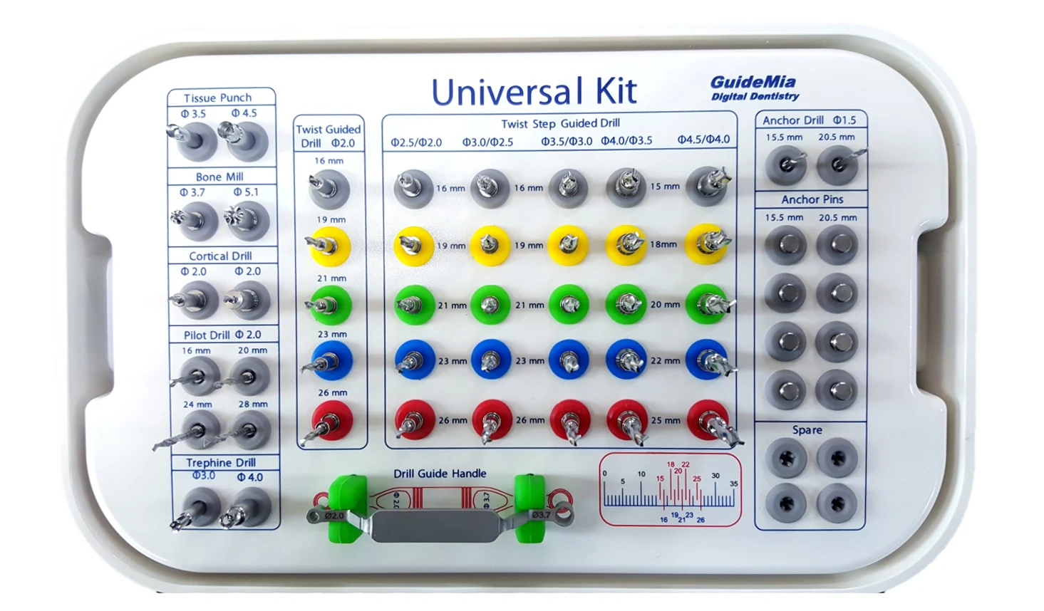
We design surgical kits and drilling sleeves. This page walks through the decisions such a design has to make, using a kit we designed as the worked example throughout: the GuideMia Universal Kit.
Start with the sleeve
The sleeve is where the plan becomes a constraint. Everything else in the kit is shaped by what the sleeve carries, so it is the first decision rather than a detail to settle later.
The example system works with four sleeve diameters:
| Sleeve | Carries |
|---|---|
| 5.1 mm | Wide-diameter drills and any tool with a 5.1 mm guiding cylinder |
| 3.7 mm | Regular and narrow-diameter drills, and tools with a 3.7 mm guiding cylinder |
| 2.0 mm | 2.0 mm twist drills, for pilot drilling |
| 1.5 mm | Anchor drills and anchor pins |
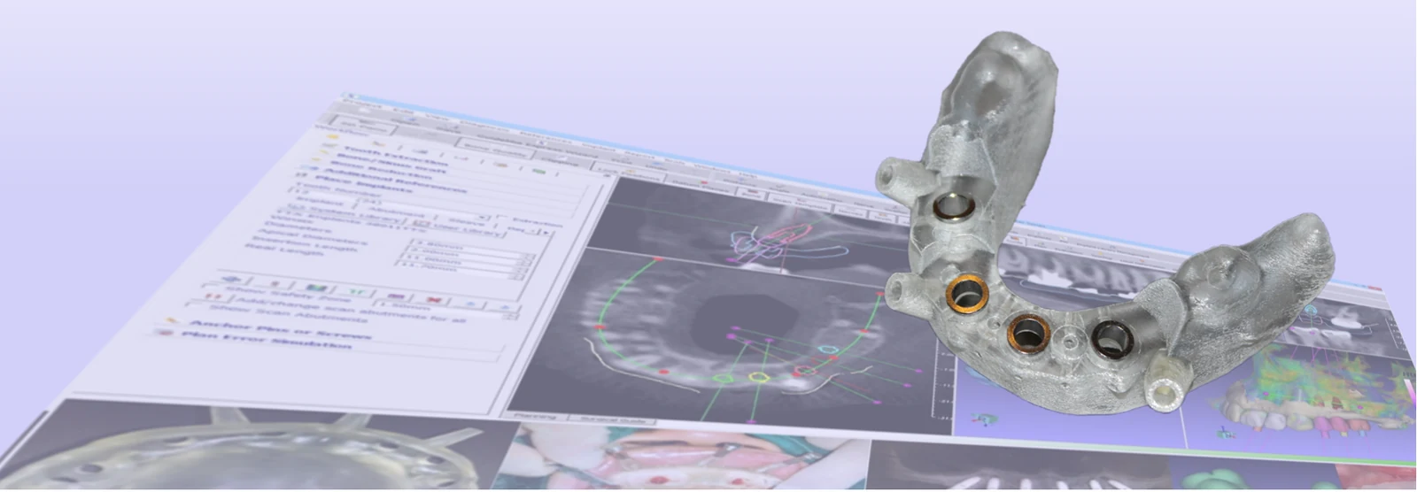
Sleeve geometry is itself a design variable. Slots, threads and other variations are configured in the planning software, so the guide that gets printed already carries the sleeve the kit expects.
Decide how a drill finds the sleeve
There are two ways to keep a drill concentric with the sleeve, and the choice shapes the whole instrument range.
A guiding cylinder is machined onto the tool itself. The tool goes straight into its matching sleeve, with nothing between them.
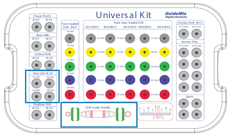
A handle steps a smaller tool into a larger sleeve. In the example kit one handle carries both reductions: a 3.7 mm tool into a 5.1 mm sleeve at one end, a 2.0 mm tool into a 3.7 mm sleeve at the other. That matters for implants wider than 3.5 mm, where the sequence runs smaller drills with the handle up to 3.5 mm, then larger drills directly in the 5.1 mm sleeve.
The guides designed for this kit accommodate 1.5 mm anchor drills, 2.0 mm pilot drills, and 2.0–4.5 mm guided drills on 3.7 mm or 5.1 mm guiding cylinders.
Set the prolongation
Prolongation is the distance from the top of the guide to the top of the implant. It is the number that ties the guide, the drill lengths and the planned depth together, and a kit has to commit to how it behaves.
The example kit carries two prolongation values — a smaller one for drill diameters above 3.5 mm, a larger one below — and both can be reduced by up to 2 mm in the planning software, with the drilling sequence changing to match. Reduction is what a posterior site usually needs, where there is not enough inter-arch space to enter the osteotomy at full length.
The design consequence is that a tool with a long guiding cylinder can reach bone before its stopping flange reaches the sleeve. The kit's instructions therefore tell the surgeon to stop on whichever comes first, rather than assuming the flange is always the limit.
Choose the preparation instruments
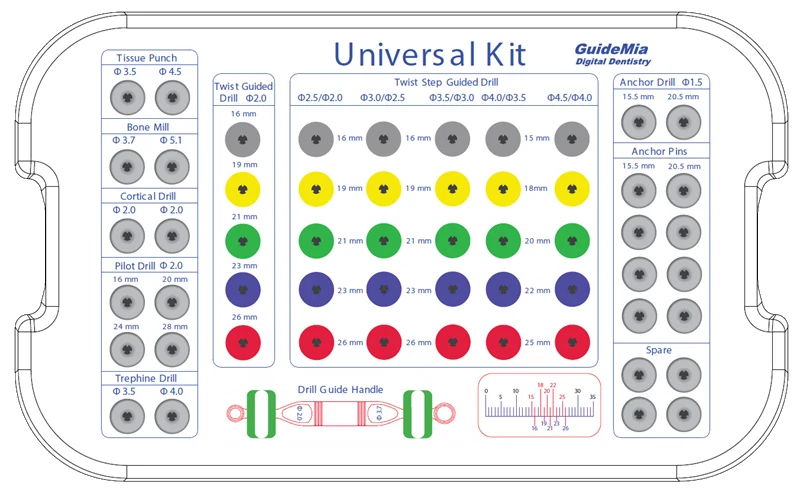
Tissue punches cut gingiva before flapless surgery, in 3.5 mm and 4.5 mm to suit the fixture platform. The 3.5 mm punch runs a 3.7 mm guiding cylinder, the 4.5 mm punch a 5.1 mm one, and each carries two prolongation values separated by a laser mark. They have no stopping flange, and the guide is removed afterwards to clear the punched tissue. 30–100 rpm.
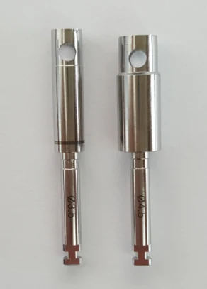
Cortical drills perforate the cortical plate through the sleeve, in 3.7 mm and 5.1 mm and two prolongations. They are advanced until the guiding cylinder is engaged in the sleeve before activation, and — because tissue thickness and platform position vary — they will not always reach the stopping flange. 1200 rpm.
Bone mills remove crestal bone for abutment seating after the guide comes off, or flatten a site before drilling, in 3.7 mm and 5.1 mm. The 3.7 mm mill has a 10 mm prolongation value and can be run to 9 mm using its laser mark. A stopping flange gives an exact platform plane. Where the guide's prolongation is smaller than the mill's, the depth has to be marked by the user — an O-ring is the usual method. 50–150 rpm.
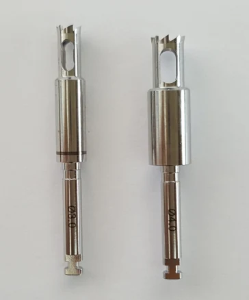
Trephine drills remove or harvest bone, in two diameters matched to the two sleeves and their prolongations. 800–1200 rpm.
Choose the guided drills
Pilot drills are 2.0 mm straight twist drills in four lengths — 16, 20, 24 and 28 mm. They are depth-specific: a flange stops the drill as it meets the sleeve or handle. When the guide is designed, the planned depth is set to match the drill length, which is what makes the pair work.
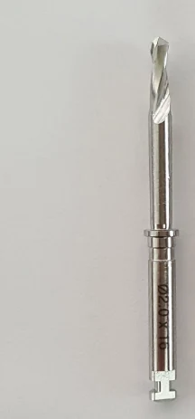
Twist and step guided drills come in six diameters and five lengths, in three working groups:
- 2.0 mm — 3.7 mm sleeves for implants under 3.5 mm, or with the handle for larger
- 2.5, 3.0, 3.5 mm — 3.7 mm sleeves, or with the handle for larger
- 4.0, 4.5 mm — 5.1 mm sleeves
Colour identifies length across the whole range, which is what makes the tray readable mid-surgery rather than a grid of similar metal.
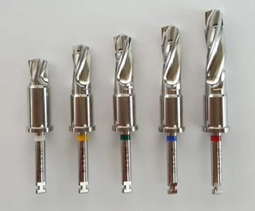
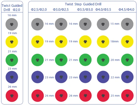
Guided drills are inserted as far as they will go before activation, and never while rotating. 800–1200 rpm.
Anchor the guide
A guide that moves has spent its accuracy. Anchor drills are 1.5 mm twist drills in 15.5 mm and 20.5 mm, prepared through 1.5 mm sleeves while the guide is held firm; anchor pins then hold it to the jaw. Neither is forced — into bone or into the guide. With the right guide design the anchor drill doubles as a pilot drill. 800–1200 rpm.
Name every part
A kit is reordered, inventoried and written about for years. The example kit names each part with two letters and two numbers: the letters identify the instrument, the first number its diameter, the second its length, with the length omitted where only one dimension is marked.
BM37 is a 3.7 mm bone mill. TS2526 is a twist step guided drill, 2.5 mm,
26 mm long. Trivial to design in, and the thing a distributor will thank you
for.
Group the kit into working sets
A full tray is not how a kit is used. The example kit resolves into four logical groups, each a complete set for one kind of case:
- 2.0 pilot kit — four 2.0 mm twist drills, for pilot-only guides
- 2.0 pilot kit with handle — the same four, plus the small end of the handle
- Guided kit, narrow platform — up to 3.5 mm, on 3.7 mm sleeves
- Guided kit, wide platform — up to 4.5 mm, on 5.1 mm sleeves
Each group corresponds to a kit definition in the planning software, so a plan is made against the instruments that will actually be on the tray.
Write the drilling protocol
The protocol is part of the kit design, not documentation written afterwards. Choosing guiding cylinders decides the sequence, and the sequence is where a surgeon meets that decision.
A drill is only guided once its cylinder is inside the sleeve. That single constraint rules out starting at the final length: a long drill whose cylinder still sits above the sleeve is unguided, and cannot be used at all.
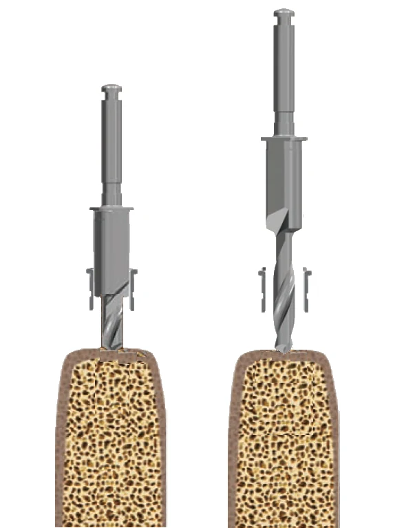
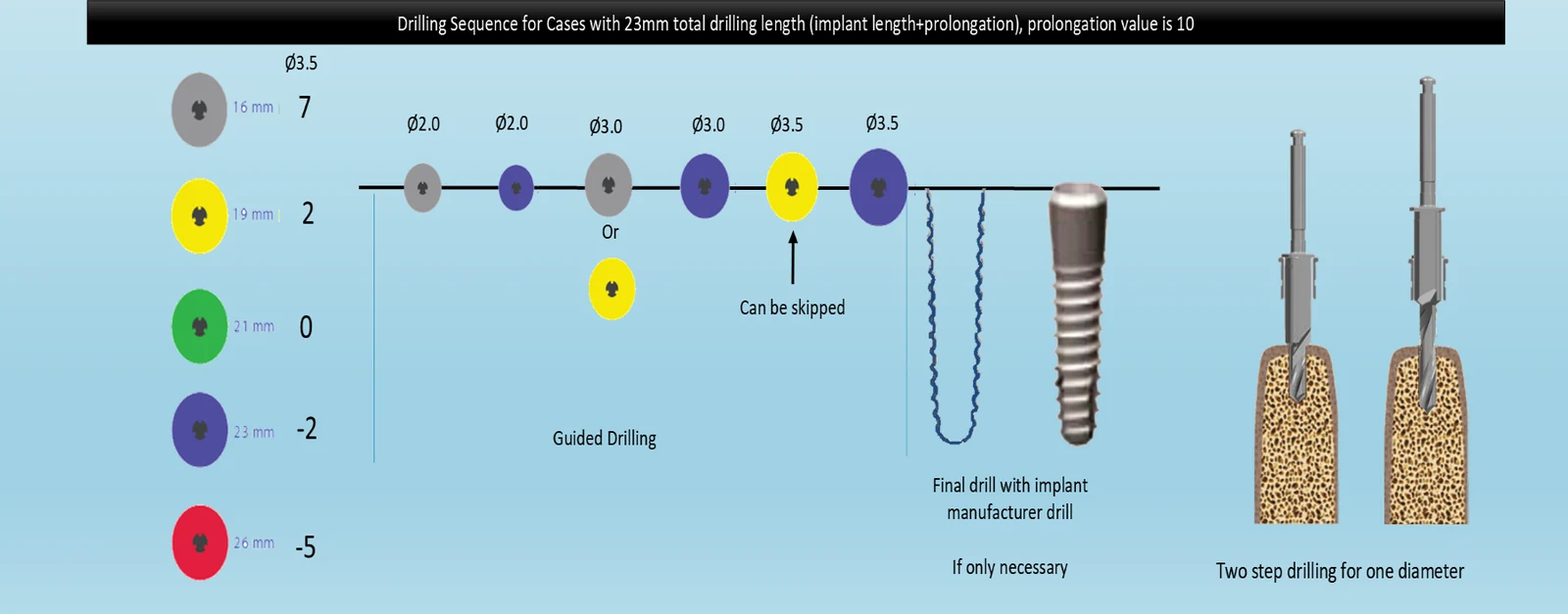
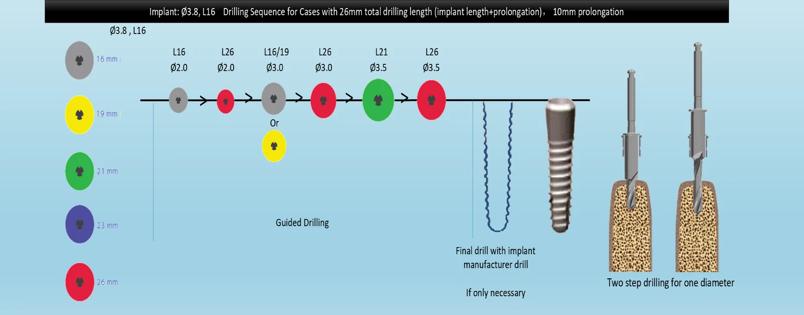
So one diameter often takes two lengths. The short drill opens the hole first. The longer drill then enters the hole already made, which lets its cylinder reach the sleeve — and only then can it cut to depth. Once a pilot hole exists, wider drills follow the same rule.
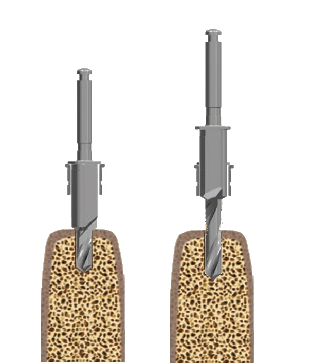
The final diameter is chosen, not matched. The guided drills are cylindrical and their apical diameter sits slightly under the upper cutting part, so the last drill is selected against the bone and the implant rather than by copying the implant's number.
The sequences those rules produce
Total drilling length — implant length plus prolongation — is what selects the sequence. Four worked cases, each in hard bone with the final diameter chosen one step under the implant:
Implant 3.8 mm × 9 mm. Total drilling length 19 mm, prolongation left at the software default, final diameter 3.5 mm.
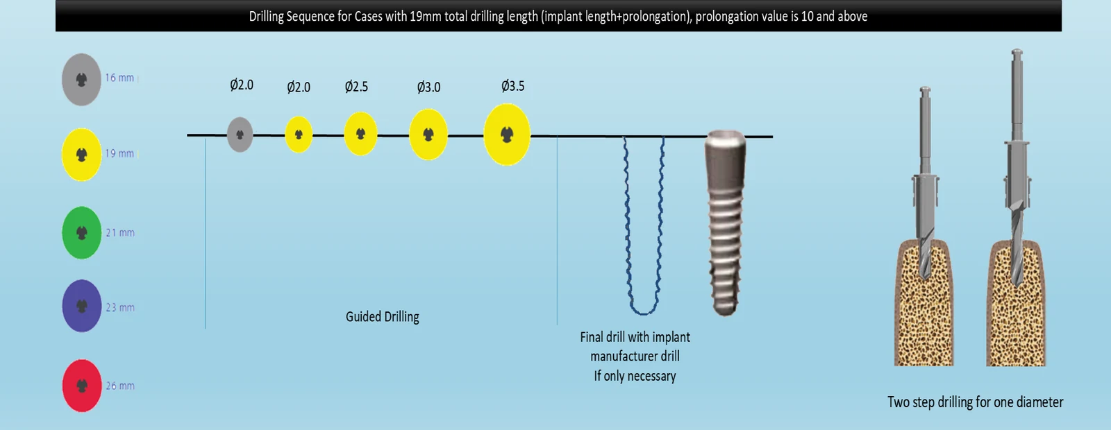
Implant 3.8 mm × 13 mm. Total 23 mm, prolongation set to 10 mm, final diameter 3.5 mm. The longer osteotomy is where two lengths for one diameter start to appear, and where a step can sometimes be skipped.
Implant 3.8 mm × 16 mm. Total 26 mm, prolongation 10 mm, final diameter 3.5 mm. The same implant diameter as the first case, three times the depth, and a visibly longer sequence.
Implant 5.0 mm × 14 mm. Total 23 mm, prolongation 9 mm, final diameter 4.5 mm. A wide platform changes what guides each step: everything up to 3.5 mm is guided by the handle with the 3.7 mm laser marking, and everything above it by the drill's own guiding cylinder in the 5.1 mm sleeve.

Plan for reprocessing
Instruments are cleaned in alcohol, rinsed in distilled or running water, dried, and returned to a tray that has to survive the cycle as many times as the instruments do. Tray material, insert retention and the legibility of the printed layout after repeated sterilisation are design decisions, and they are easy to leave until too late.

Design yours
The kit above exists because each of these decisions was made deliberately and then tested against real cases. We do the same work for other systems: surgical kits and drilling sleeves designed around a specific implant platform, its prolongation behaviour, its drilling sequence and the guides that will carry it.
If you are building a guided system, or changing one, tell us what platform it has to serve and we will come back to you.