
How accurate is a guided implant surgery? How much has that accuracy changed over the years? After so many surgical guides, do you know what the accuracy of your next one will be? These questions have been putting the industry on the spot for more than a decade, and the honest answer is that most of the people asked cannot give a number they would defend.
Since digital implantology arrived in the 1990s, everything around it has improved. A desktop CPU went from a single core at 100 MHz to twelve cores at 3 GHz. Memory went from 64 MB to effectively unlimited. Imaging went from medical CT to CBCT, the X-ray dose from around 7000 units to 70, the slice thickness from 0.75 mm to 0.1 mm. Those advances are what put digital implantology inside ordinary clinics.
Accuracy did not get the same systematic attention, and the question hides a second one that is rarely separated from it: the accuracy of the surgical guide and the accuracy of the surgery performed with it are two different things.
Published studies usually run the same way — take a handful of cases, make some guides, drill into models, measure, report. The reported ranges vary widely, though roughly 1 mm of linear error and 5 to 6 degrees of angular error is typical. Almost all of that work shares a set of methodological problems. Researchers generally use experimental software rather than the systems that actually produce guides, so the results say little about the guides made in daily practice, and the tools, sleeves and printers used are far from the ones in clinical use. Which part of the error is systematic, which is random, which comes from the operator and which from the experimental design is seldom examined. And the work is usually done without much insight into the software: the factors inside the algorithms that drive accuracy are not something a study can control for if it does not know what they are.
There is also a persistent piece of folklore worth naming. Users are often told that after a software system registers an optical scan to a CBCT, they should fine-tune the result by hand. Try it and the problem becomes obvious: adjusting a three-dimensional position through two-dimensional views is close to impossible. A registration that needs to be nudged by hand is telling you something about the registration, not about the user.
GuideMia Implant Master has been FDA 510(k) cleared since 2012 (K121466) and is used in more than a dozen countries. What follows is what the dental implant software, the surgical kit and the process around them actually do to control accuracy — written from the inside, by the people who wrote the algorithms.
What the accuracy of a surgical guide is made of
Four separate things are folded into the word "accuracy", and it helps to keep them apart:
- Shape accuracy, or fit — whether the guide sits flush on the cast or in the patient's mouth.
- Positioning accuracy — whether the guide, once seated, reproduces the position it had in the plan.
- The effect of the guide on the drilling — how faithfully the osteotomy follows the planned axis and depth.
- Stability during surgery — whether the guide stays where it was put while the drills run.
CBCT data processing in dental implant software
For a partially edentulous case designed from optical scans, the quality of the CBCT processing decides the positioning accuracy of the guide. For a fully edentulous case, or a bone-supported guide, it decides both the shape and the positioning.
When implant planning software was limited by the hardware it ran on, the common trick was to down-sample the volume. A 512 × 512 × 512 dataset holds 125 million voxels and upwards of 250 MB, and between loading and display that data may be copied three or four times, so a gigabyte disappears before any image processing starts. Halving each axis to 256 × 256 × 256 leaves one eighth of the data — and the graphics hardware can then interpolate the survivors back into a smooth-looking rendering, which hides what was thrown away. Seven eighths of the patient's scan is gone. Treating the input data with respect is the first principle of any serious system, and with today's hardware there is no longer an argument for the shortcut.
The second requirement is the reconstruction of low-density bone. A simple threshold is never the end of it: the porous structure left on the bone surface has to be processed properly before the model is usable. GuideMia Implant Master does this with what it calls virtual tissue peeling, and the resulting model is what makes 3D printing and bone-level guide design possible at all. Doing it inside the dental implant software matters as much as doing it: the bone model that arrives at the guide-design step is then the one the planner inspected, at the resolution the scan supports, rather than a version that has been out to a general-purpose modelling tool and come back re-smoothed to someone else's standard.
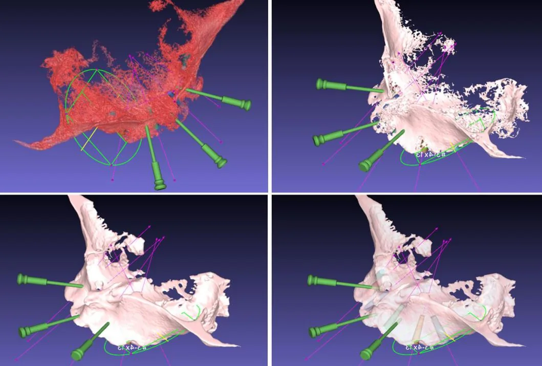 The image processing of a maxillary case — filling and smoothing the reconstructed bone.
Where the bone model is good, the guide can be built against the bone surface rather than floating above it. That is what makes a combined bone-reduction and implant guide practical.
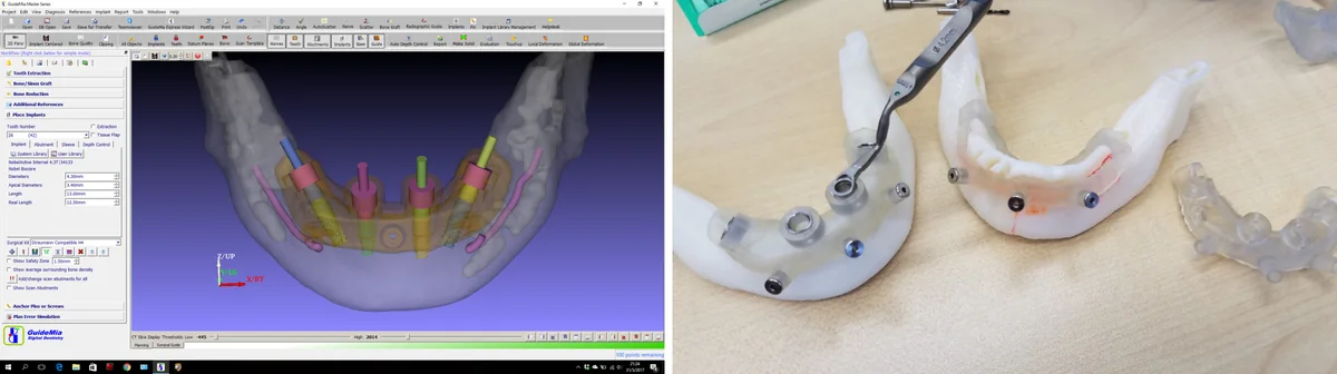 A bone-reduction guide and the implant guide that follows it. Courtesy of Dr. Raymond Chow, Hong Kong Dental Implant Center.
Registering the scans
Most people picture registration as picking three or more points on each dataset and letting an iterative-closest-point algorithm pull them together. That picture is exactly why registration accuracy is often poor — and why the subject has been made to sound harder than it is, complete with the advice to adjust the result by hand afterwards.
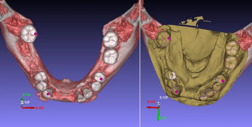
The weakness is in the premise. CBCT data is not precise enough for point-picking, and an operator cannot reliably choose corresponding points on two datasets of different kinds. Below, the points selected on the two windows are visibly not the same points.
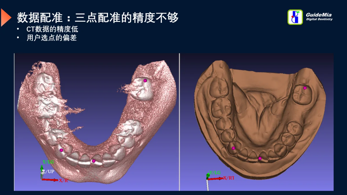 The same landmark, picked twice — and not in the same place.
GuideMia Implant Master registers regions, not points. From the point the user indicates, the dental implant software selects a neighbourhood whose local CBCT characteristics suit matching, and a region-matching algorithm does the rest. It is fast, it tolerates imprecise picking, and in the large majority of cases it succeeds on the first attempt.
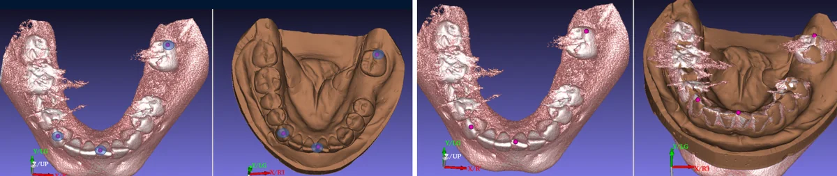 Registration built from several matched surface patches rather than single points.
There is a temptation, in software generally, to automate a step past the point where automation helps. Registration attracts that temptation. But CBCT has lower resolution than an optical scan and carries scatter, and a fully automatic match over a large region has plenty of ways to go wrong. The case below — a patient with mobile teeth — is the argument for choosing the regions deliberately: the teeth that moved between the two scans must not be the ones the registration trusts.
 With mobile teeth, which regions are matched is a clinical decision, not a detail.
For fully edentulous cases, and for partially edentulous cases with heavy scatter, GuideMia Implant Master registers the patient's CBCT to the radiographic guide automatically: it finds the radiographic markers, extracts them and matches them, and it does so even when the scan is full of artefacts. The orientation the scan happens to be in does not matter.
A common alternative is to register an optical scan of the radiographic guide to the CBCT by hand — points on the STL surface, matching markers in the volume. It is an awkward operation. The points on an STL sit on surfaces with a clear orientation, while the markers in the CBCT have almost none, so making a point on a sphere correspond to a point on a mesh is guesswork, and there is no good way to automate it.
It is worth adding that a triple-scan protocol is sometimes used to get around errors in CBCT processing: register the CBCT of the radiographic guide to the patient's CBCT, then register an optical scan of the guide to its own CBCT. That does improve the shape accuracy of the finished guide, and its stability. The positioning error, however, still rides on the CBCT processing, and no amount of optical scanning removes it.
Geometric detail, and what to remove
Guide-design algorithms usually have two steps: copy the geometry of the model, then remove the undercuts. A third step is missing more often than not — dealing with the fine geometry of the optical scan.
Dental models carry small bubbles and plaster residue, and teeth carry a great deal of genuine fine detail. Reproduce all of it faithfully in the guide and the guide will not seat: every artefact becomes an interference. The dental implant software has to decide what is anatomy and what is noise, and take the noise out.
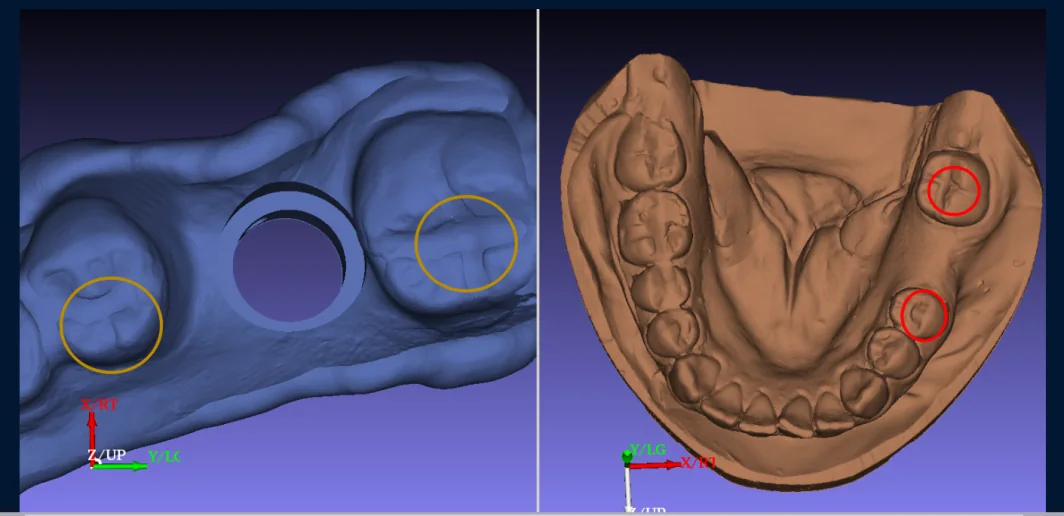 Small surface detail removed from the guide's fitting surface, so the guide can seat.
Undercuts, fit analysis, and the insertion path
Full-arch guides make undercut processing special: a single mishandled point anywhere on the arch can stop the guide seating. Some approaches to removing undercuts trade away the accuracy of the fitting surface to do it — the guide goes on, but it is no longer the shape that was designed.
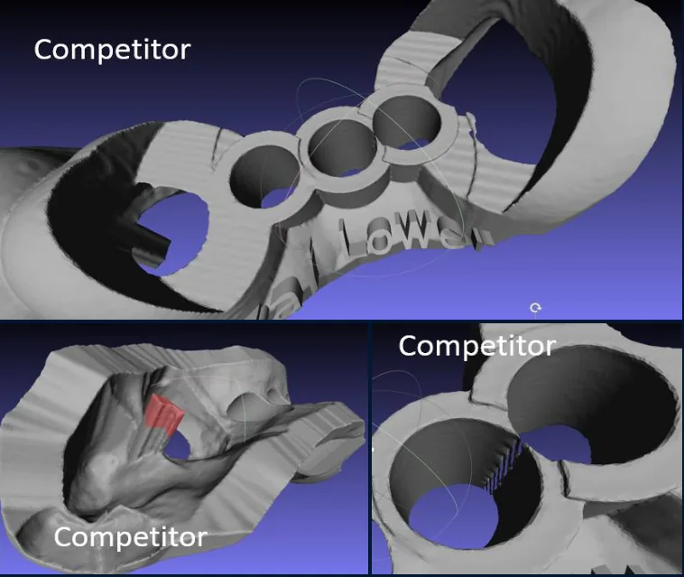 Removing undercuts at the cost of the surface the guide is supposed to reproduce.
GuideMia Implant Master removes the undercuts and keeps the designed surface.
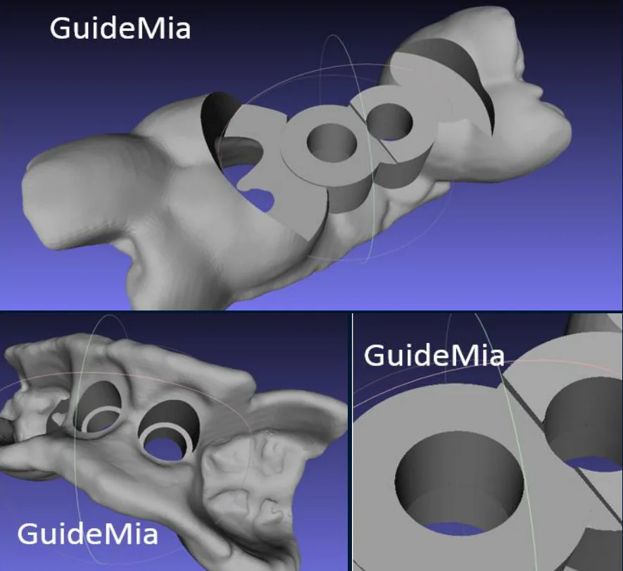 The same operation with the fitting surface preserved.
Removing undercuts requires an insertion path, and the algorithm works around that direction. In the fit analysis below, the green areas are the clearance left after the undercuts are taken out.
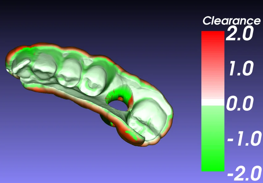 Fit analysis: clearance between the guide and the patient's anatomy, in millimetres. This visualisation is patented GuideMia technology.
That clearance is also where the surgery can go wrong. Seat the guide along its insertion path and the fit is as designed. Press it from the buccal side instead, and it tilts — and the tilt is multiplied down the length of the osteotomy.
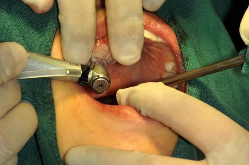 Seating the guide the way it was designed to be seated.
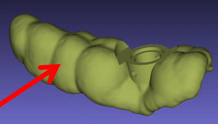 Pressing from the buccal side. The guide tilts, and the drill follows it.
The insertion path is a design decision, not a fixed property of the case. Redefine it in the dental implant software and a different guide comes out — one whose buccal and lingual surfaces both sit against the patient's tissue.
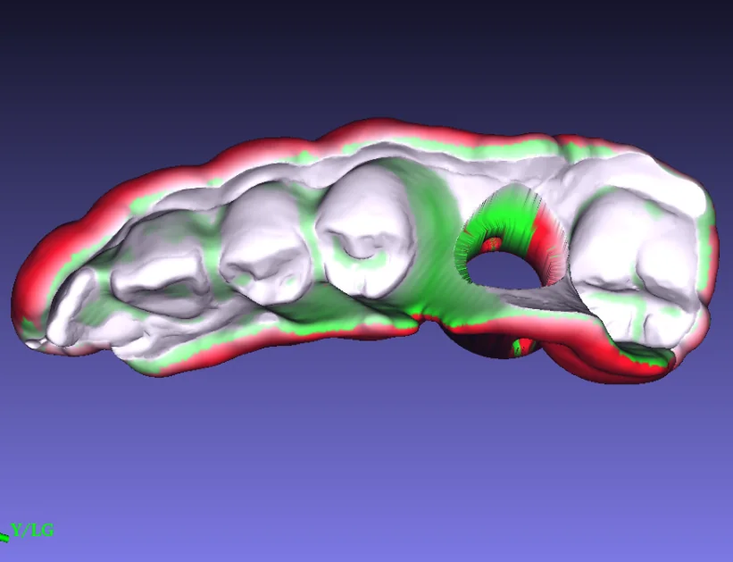 The same case with a different insertion path: contact on both sides.
Undercut processing therefore acts directly on both the accuracy and the stability of a surgical guide, and it is the step most often left unexamined.
Checking that the guide is actually seated
In normal practice, when a guide is placed the surgeon checks that both ends are down and that it is neither loose nor tight. Whether the guide is sitting exactly where it sat in the plan — same coverage, same direction — is something nobody can see.
GuideMia Implant Master has a little-known answer to this. Once the guide is designed, the system can generate a separate part whose only job is to verify the seating: with the guide in place, the relationship between the guide and that part tells the surgeon whether the guide is where it should be.
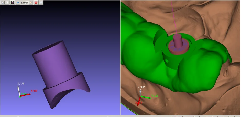 A part generated alongside the guide, purely to confirm that the guide is seated as planned.
The surgical kit
A guided kit that navigates through a spoon or handle held against the guide introduces a gap at every interface, and those gaps add up along the drill. Take a kit whose sleeve is 3.5 mm tall, assume a 0.1 mm gap between the spoon and the sleeve and another 0.1 mm between the drill and the spoon, and for an 11.5 mm implant the apical deviation can exceed 1 mm — from tolerances alone, before anyone's hand enters the picture.
The GuideMia Universal Kit is built the other way round: the drill carries its own guiding cylinder and runs directly in the sleeve, with the spoon eliminated in most situations. Fewer interfaces means less accumulated play, and the drills wear less because nothing rubs where it should not. Several other details in the kit exist for the same reason.
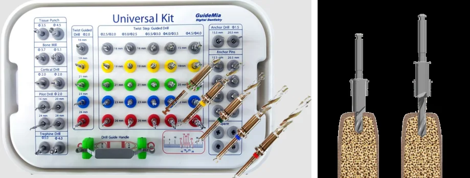 Guidance through the drill's own cylinder, running directly in the guide's sleeve.
Comparing the plan with the result
Implant placement is a skill that improves with feedback. If a surgeon cannot tell where a deviation came from, or how to avoid it next time, much of the value of working digitally is lost. Comparing the post-operative scan with the plan is what closes that loop: it shows whether the guide was seated imperfectly, whether the implant drifted mesially or distally, whether it tipped buccally, whether the guide was stable.
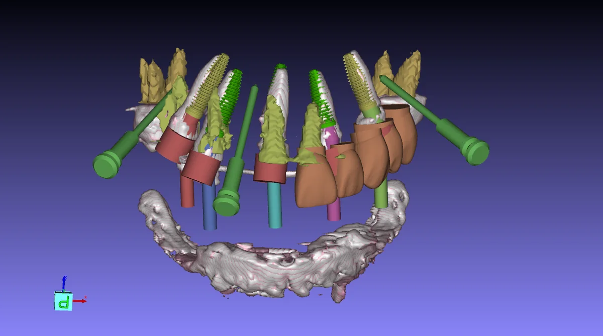 Plan and outcome on the same anatomy. Courtesy of Dr. Feng Liu, Beijing.
That feedback has changed practice. Reviewing full-arch cases this way showed guides tipping lingually often enough to matter, which led to a set of anchor-pin guidelines: the familiar left–centre–right arrangement of three pins is no longer recommended as a default, and pins should not sit in approximately one plane or point in approximately one direction.
The quality system, and the printer
Nobody enjoys quality-management paperwork, but working with labs internationally taught us where it earns its keep: standardised design procedures, standardised data management, and strict control of the manufacturing equipment.
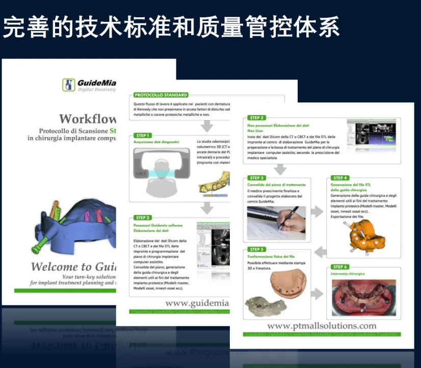 An SOP from a production quality system. Courtesy of Francesco Pastore, PTM Solutions, Italy.
The 3D printer market deserves a specific warning. Buyers and manufacturers do not share the same information, and most users have never been told what layer thickness, XY resolution, minimum feature size or post-processing do to a part. Guides get printed on FDM machines. Printers with 0.1–0.2 mm error get sold for clear aligner work, where 0.2 mm is the size of the tooth movement being planned for a whole step. GuideMia helps customers establish design and manufacturing SOPs, runs one in its own facility, and applies explicit criteria when selecting printers and scanners.
Simulating the error
The accuracy of an implant placement depends on several inputs at once: CBCT accuracy, scanner accuracy, registration accuracy, printer accuracy, and how precisely the guide seats. Each of those has a known or estimable range.
So after a plan is complete, a fair question is: given those ranges, where could this implant actually end up? GuideMia Implant Master answers it with a patented error-simulation module, which shows the positions the implant may occupy when the errors combine unfavourably. That turns the safety margin into something visible — so the planner can move away from a critical structure before surgery rather than discovering the margin was too thin afterwards.
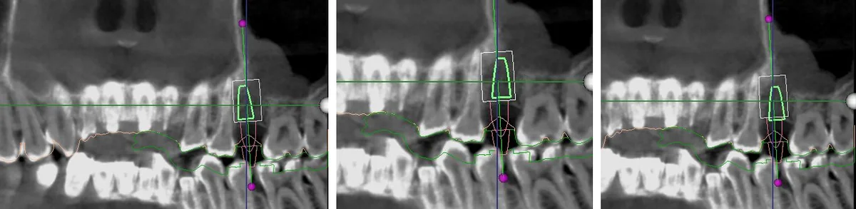 One implant, its safety zone, and several positions it could occupy under combined error.
Closing
For more than a decade GuideMia has worked on the accuracy of treatment planning, surgical guide design and the clinical use of guides, and has built the corresponding functions into the dental implant software that tens of thousands of cases have since been planned with.
One question in this field is still open, and it is the expensive one: once a surgical guide has been manufactured, can we know how accurately it will seat in the patient's mouth, and how much deviation that will cause? Today, nobody can. Everything above narrows the error; none of it measures the finished part. That measurement is the next thing worth building.
Written by Frank Gao, GuideMia Technologies, LLC. First published in 2018 and edited for the web; the technology it describes ships in GuideMia Implant Master, FDA 510(k) cleared under K121466 and developed under an ISO 13485 certified quality system.