
A guide is only as good as its agreement with the instruments that will pass through it. When a kit is not in the shipped list — a house brand, a distributor's own set, a modified tray — it can be defined rather than worked around.
This is a one-off setup task, done once per kit and then available to every case. It is not part of planning a case.
Where the kits live
Type %Appdata%\GuideMia5.0 into your file manager and press enter. The folder
name really is GuideMia5.0 regardless of the version you are running — it
kept the old name so that settings survive an upgrade.

Alongside the kits you will see the rest of the per-user state: config.dat,
GuideMiaCaseCatalog.xml, saved implant positions, a customer logo. This is
the folder to back up, and the folder to copy when you move to a new machine.
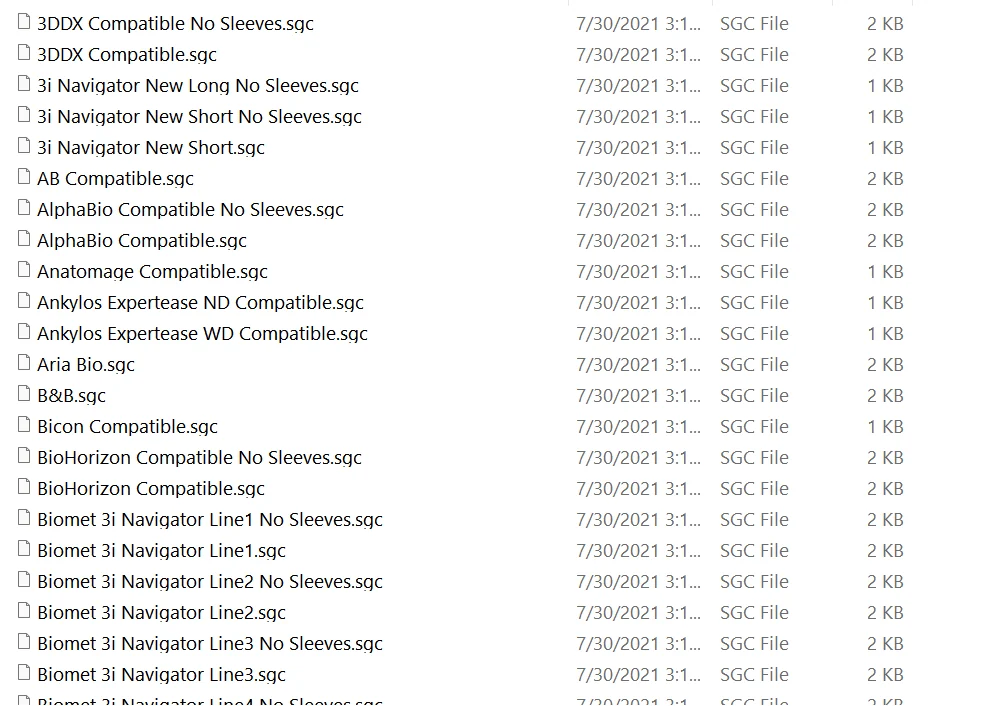
Inside are the surgical kit configuration files, named *.sgc. Each one is a
kit.
The list is long — 3DDX, 3i Navigator, AB, AlphaBio, Anatomage, Ankylos, Aria Bio, B&B, Bicon, BioHorizon, the Biomet 3i Navigator lines, and on through the alphabet. Two details in it are worth noticing before you add your own:
- Most kits appear twice, once plain and once as "No Sleeves". The second is the pilot-drill-only variant of the same kit — the guide is built to the drills rather than to a sleeve. If your case is going to be pilot-only, there may already be a file for it.
- The names carry the word "Compatible" rather than the manufacturer's own branding, which is the correct reading of what these are: kits dimensioned to match a system, not the manufacturer's own product data.
Two points about this location, both from the release notes:
- The
.sgcfiles moved into Application Data precisely so that changing a kit no longer needs administrator rights. - The system keeps the original versions alongside your customised ones under different filenames, so a customised kit appears as a new entry in the list rather than replacing a shipped one.
Defining a kit
Start from something similar. Find a shipped brand whose kit resembles yours and copy its file. There are broadly two kinds — kits that work through handles and kits that work through guiding cylinders — and starting from the right kind saves most of the editing.
Copy and rename. If the brand is "ABC Implant", copy an existing file and
name it ABC Implant Kit.sgc.
Change the name inside to match. Edit the file in a text editor and change:
KitName="GuideMiaUniversalKit MP"
to
KitName="ABC Implant Kit"
The name inside must be the filename without the .sgc. They are not
independent.
Edit the drill data. The file carries a line per drill size, and a list of drill lengths. Change them to your kit's parts.
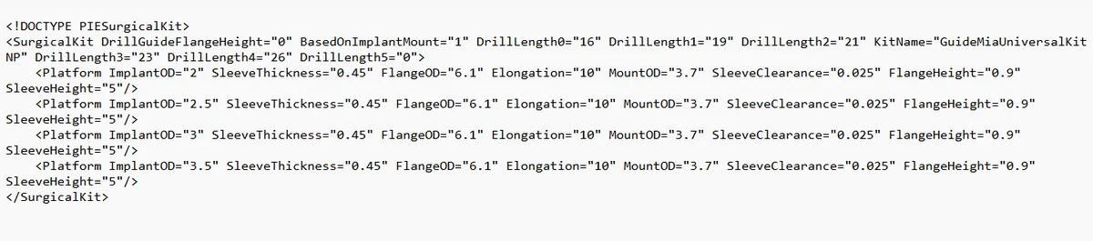
The whole format is visible in one screen. The SurgicalKit element carries
the kit-level values — KitName, the drill lengths as DrillLength0 to
DrillLength5, DrillGuideFlangeHeight, and BasedOnImplantMount — and then
one Platform element per drill size:
<Platform ImplantOD="2" SleeveThickness="0.45" FlangeOD="6.1" Elongation="10"
          MountOD="3.7" SleeveClearance="0.025" FlangeHeight="0.9" SleeveHeight="5"/>
Every attribute has a counterpart in the dialog below, which is what "one-one
corresponding" means in practice. Note that the drill lengths are a fixed set
of six slots and unused ones are "0" — DrillLength5="0" in this kit means
five lengths, not six.
Check it appears. Save into that folder, start GuideMia, go to the planning
page and list the surgical kits. ABC Implant Kit should be there.
Other shipped files carry additional data beyond this minimum; if a parameter in your kit has no equivalent in the file you copied, copy a file that has it.
Editing in the file or in the software
From here there are two routes, and they are equivalent:
One is editing the file, another one is using GuideMia software. The parameters are one-one corresponding between them.
So a kit can be built in a text editor and then refined in the interface, or the reverse. Nothing is available in one and not the other. The configuration button sits on the implant placement page, next to the kit list.
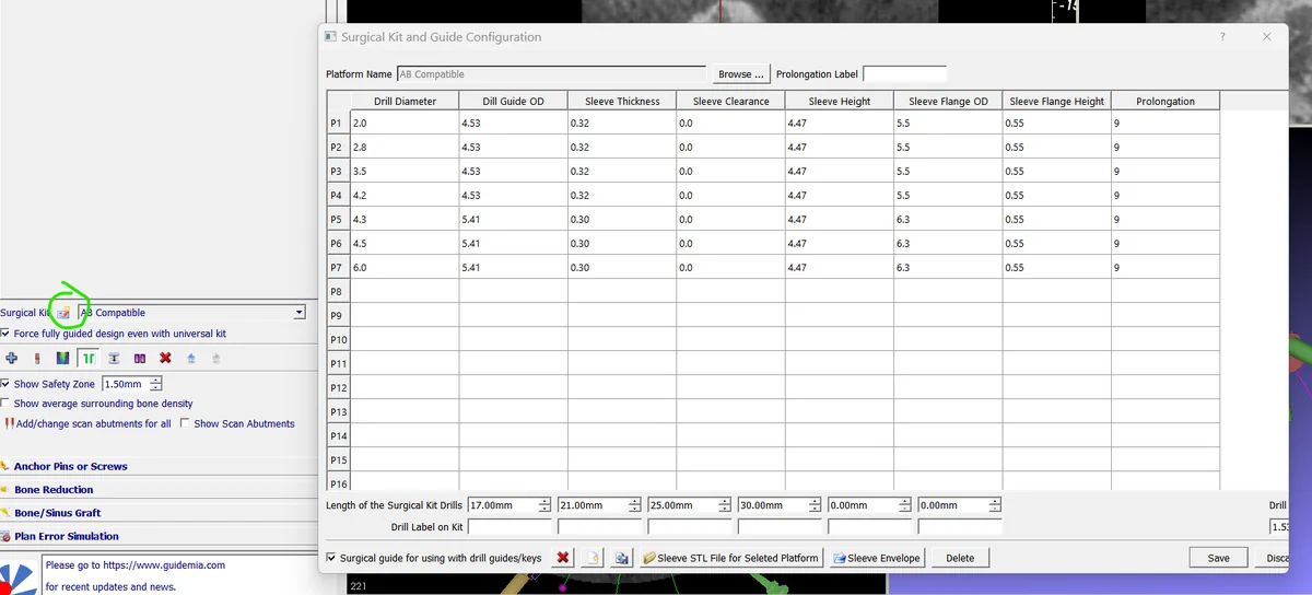
The dialog is the file as a table. Platform Name at the top is the kit, with Browse to load a different one and a Prolongation Label beside it. Below that, one row per platform — P1 to P16, so sixteen drill sizes is the ceiling — across the columns that matter:
Drill Diameter, Drill Guide OD, Sleeve Thickness, Sleeve Clearance, Sleeve Height, Sleeve Flange OD, Sleeve Flange Height and Prolongation.
Under the table, Length of the Surgical Kit Drills carries the six slots
from the file — 17.00 mm, 21.00 mm, 25.00 mm, 30.00 mm and two unused — with
Drill Label on Kit beneath each, which is where the line1/line2 naming
described below is entered.
Three controls at the bottom decide what kind of kit this is:
- Surgical guide for using with drill guides/keys — ticked for a kit that works through handles and spoons rather than guiding cylinders on the drills themselves. This is the "two kinds" distinction above, expressed as one checkbox.
- Sleeve STL File for Selected Platform and Sleeve Envelope — the two models each platform needs. See below.
- Save / Discard, and Delete to remove a platform row.
One option on the panel behind the dialog is worth knowing about because it changes what the software will let you do: Force fully guided design even with universal kit. Without it, a case falling back to the universal kit is treated as pilot-only.
What the parameters mean
Drill guide OD is the size of either the handles and spoons, or the guiding cylinders of the drills — whichever mechanism the kit uses. This is the number the guide's holes are built to.
Sleeve parameters follow a generic sleeve shape. The wider part is the flange. The clearance values exist so the hole in the printed guide actually accepts the sleeve — they are the manufacturing allowance, not a design preference, and setting them to zero produces a guide that will not assemble.
Drill lengths are measured as the total length from the top of the guiding area, where there is one, to the tip. Not the cutting length, and not the catalogue length of the implant.
Each length can carry a name — line1, line2 and so on — which is worth
using, because those names are what you will recognise later in the drilling
sequence rather than a bare number.
Customising the sleeves
Sleeves are defined per platform — one per line of the kit file. Each sleeve needs two models, and both are required:
The sleeve model. The sleeve itself, as an STL. The coordinate system is not negotiable: origin at the top centre, Z pointing down, and X along the mesial-distal direction. A sleeve modelled on any other convention will load and be wrong.
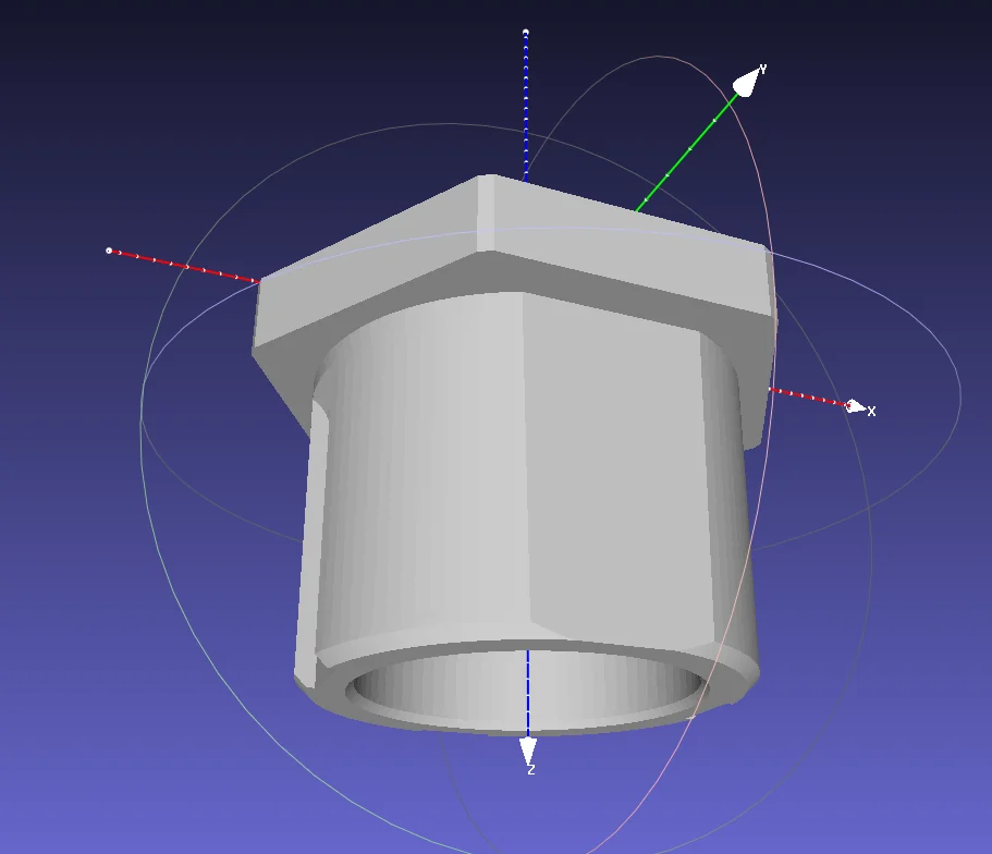
The Z arrow pointing down from the origin is the check to make before you save anything. It is the opposite of the implant convention on the implant library page, where Z points to the tip of the fixture, and getting the two confused is the common mistake.
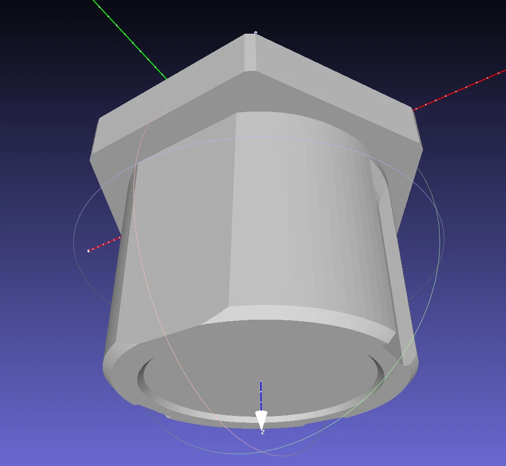
The shape itself is ordinary: a cylindrical bore that the drill passes through, and a wider flange at the top that seats on the guide. What the guide is actually built around is not this part but its envelope.
The envelope model. A shape that encloses the sleeve — this is what the guide is cut around, so it defines the void, not the part. It must have no holes, no undercuts and no horizontal grooves, and vertical grooves are better removed too. Anything the envelope cannot express becomes a feature the guide cannot be printed around.
Load both with the buttons on the sleeve page; when you save, the system copies the files into the application data folder alongside the kit definition. Every line of data in the kit configuration needs both files specified. Once they are, the kit is ready to use.
A note on versions
The screenshots on this page are V8. The kit and sleeve pages have moved between releases — the configuration button is on the implant placement page now, and the bone reduction work was split between planning and guide design in V6 — so if you are running an older build, expect the same parameters under a different arrangement of panels and icons. The file format and the meaning of the values have been stable; the interface around them has not.
Related
The GuideMia Universal Kit is the worked example of a kit designed to these conventions, with its sleeve diameters, guiding cylinders and drill lengths set out in full. It is also the kit the software falls back to when an implant has no matching kit of its own.
- Expanding the implant library — the other half of the same setup: the implants a kit is matched against
- Placing the implant — where a kit is chosen for a case
- Designing the guide — where the sleeve system is applied to the geometry