
Everything downstream is measured against the bone model. The nerve is drawn relative to it, the implant is judged against it, and in a CT-only case it becomes the surface the guide sits on. This step decides how faithful all of that is.
If you said yes at the start
The AI engine was offered the whole jaw when the project opened. If you accepted, this step is review — the Wizard says so:
You can skip this step if AI segmentation has already been done.
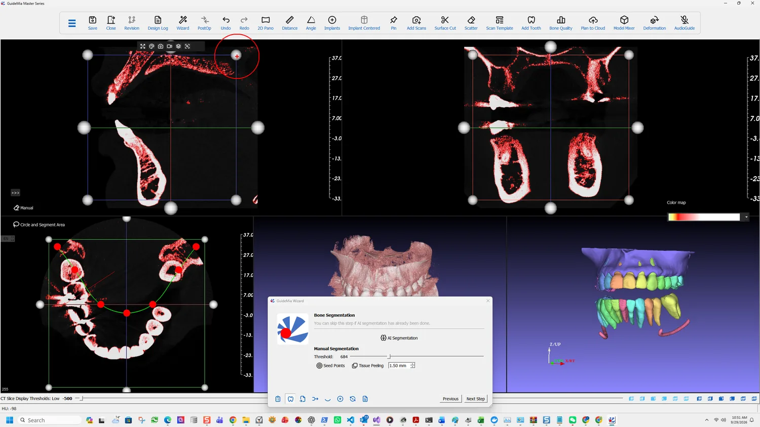
AI segmentation produces roots, bone and the nerve channels together, which is why both this page and the nerve page become checks rather than work. The 3D view arrives with every tooth already separated and coloured.
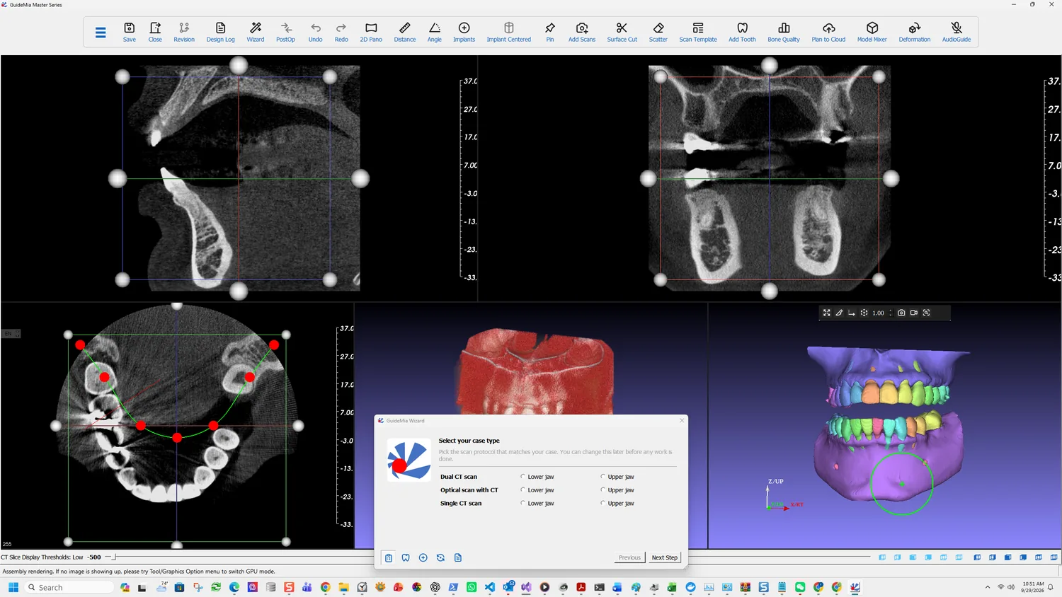
What there is to check is whether the separation is right where it matters — at your implant site and its neighbours. Hide the bone structure and the roots come into view underneath it:
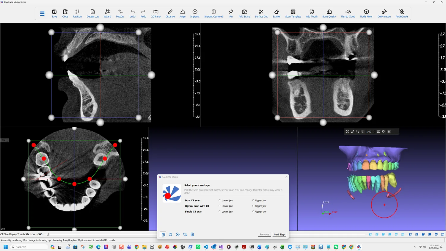
Roots are the reason this matters beyond appearances. The clearance between a planned fixture and an adjacent root is judged against these models in step 7, so a root the AI merged with its neighbour is a check you will not get.
It runs in two stages, and they behave differently:
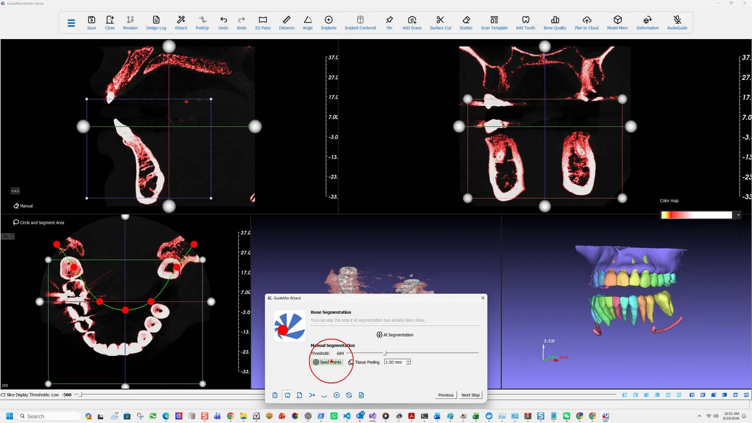
The segmentation has two stages. The first stage is CBCT segmentation. While it is running you can continue your design. The second stage is actually to create 3D geometries. At that time, you would need to wait till it is finished.
So the first half costs you nothing; the second is a wait. If you declined at the opening prompt, the AI Segmentation button on this page starts the same work — you have simply lost the head start.
Doing it by hand
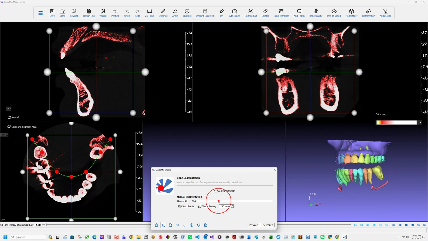
Manual segmentation takes three inputs, in this order. The order matters: seed points placed before the thresholds are right will select the wrong thing.
Thresholds
The values are Hounsfield units, as in the CBCT data itself. Properly calibrated data runs from −1024 to under 10000, though some scanners produce a wider range.
As you move the threshold, two things update at once: the filtered area in the 2D slice windows, shown in red, and the 3D rendering. You are not working blind, and you are not aiming at a number — move it until the selection represents the patient's hard tissue.
Region of interest
Each 2D window carries a box with handles. Resize them so the box contains the jaw you are working on and no more. Everything outside it is excluded from the segmentation, which is the cheapest way to drop the opposing arch, the cervical spine and the scanner's own artefacts.
Seed points
Thresholding alone leaves disconnected components and areas you do not want. A seed point picks the part you mean, and one is usually enough:
Scroll through your 2D slices, and click a point on any of the views. In a typical scenario, for example, you are going to work with lower jaw, you can just pick a point in the lower incisor area. Do not pick the black area because the pixels there will be discarded after the thresholding.
That last sentence is the one that catches people. A seed dropped where the threshold has already excluded the voxels selects nothing, and the result looks like the tool is broken.
Use more than one seed only when you genuinely want separate areas.
Tissue peeling
The Wizard's segmentation page carries a Tissue Peeling control with a size in millimetres — 1.50 mm in this case. It is not a cosmetic smoothing pass:
This tissue peeling operation is used to fill in the holes on the bone surfaces and generate smoother bone model. Sometimes patients' bone dentistry is low, it is almost impossible to create a good solid model of the bone structure for 3D printing or bone level surgical guide design.
The parameter is roughly the size of the holes to fill — normally 1 to 3 mm or slightly larger. Reach for it when the bone is porous enough that the segmented surface comes out full of gaps, which is exactly the case where a bone-level guide would otherwise be impossible.
The same tool, other tissues
This is not only a bone tool. Lower the thresholds and the same three inputs segment soft tissue, or an empty space such as the sinus. The tool selects whatever the threshold admits; bone is simply the usual answer.
The full Segmentation page in the workflow panel splits into three tabs — Bone, Template and Teeth — where the Wizard shows only the bone work. It also carries:
- Circle and Segment Area, which segments a circled area of the current bone structure into its own surface model. That model can be exported, or combined with further segmentations to build a bone-level surgical guide.
- The Virtual Tissue Model page, for cases where the soft tissue has to be represented rather than inferred.
A note on what you are looking at while you work: the two 3D windows have different jobs. The right-hand assembly window shows everything; right-click an object there to make it current, and it appears alone in the left-hand working object window. Hide removes an object from view without deleting it, which is how you get the bone out of the way to look at the teeth beneath it.