
GuideMiaGuideMia Technologies, LLC

GuideMia OrthoPlus

Quick Start Guide

An aligner case from two scans to printable arch models or direct-print aligner files, in thirteen steps. The whole guide on one page — every control named as it appears on screen.

27565 words65 figures13 steps

Front matter

Intended use and safety

What GuideMia OrthoPlus is and produces, its indications for use, intended users, warnings, and the boundary between what the system does and what remains the clinician's judgement.

What GuideMia OrthoPlus is

GuideMia OrthoPlus is a Windows desktop application for orthodontic treatment planning and appliance design. It takes intra-oral scans — and, where you have one, a CBCT volume — separates the individual teeth, produces a treatment plan, stages the movement into steps, and writes out files you can manufacture from.

Everything happens in one program, on your own machine, in one project file. There is no separate module to launch, no intermediate file to hand between tools, and no second application to install. Segmentation, planning, staging, attachments, model generation and reporting are all pages of the same workflow, and the case carries all of them. If you have the case open, you have everything open.

Projects are saved with the extension .gos; a packaged project, the form you send to someone else, is .gos.gpk.

What the software produces:

OutputUsed for
Arch models, one per stepPrinting, then thermoforming aligners over
Aligner and retainer shellsPrinting directly, no thermoforming
Aligner boundary filesReviewing and adjusting the cut line of each shell
Aligner trimming pathsDriving a robotic trimmer
Bracket bonding guidesIndirect bonding of fixed appliances
A combined model of teeth, gums and attachmentsVisualisation and case sharing
A treatment reportPresenting the plan

Two strengths are worth knowing about before you begin, because they change how you work. The first is that automation is offered at every stage rather than in one place: the Happy Button described in step 1 will do the next step of the workflow for you at any point, and AlignerBot will run a whole case end to end. The second is that everything runs on your own machine. Cases are not uploaded for processing, and the AI Engine that performs segmentation is a local program.

Indications for use

"GuideMia Ortho+ software system is intended for use as a medical front-end device providing tools for management of orthodontic models, systematic inspection, detailed analysis, treatment simulation and virtual appliance design option (Custom metal bands, export of models, Indirect Bonding) based on 3D models of the patient's dentition before the start of an orthodontic treatment. It can also be applied during the treatment to inspect and analyze the progress of treatment. It can be further used at the end of the treatment to evaluate if the outcome is consistent with the planned/desired treatment objectives."

Use of the system requires the necessary domain training and knowledge in the practice of orthodontics, as well as dedicated training in the use of the software.

Intended users

The system is for dental professionals in dental offices, dental laboratories and treatment planning centres. In practice one person usually runs a whole case, but the responsibilities divide roughly three ways:

  • Dentists, oral surgeons and physicians — diagnosis tools, treatment plan review and adjustment, guide review, plan approval.
  • Planners — data preparation, treatment planning, and model design.
  • General — all system functions.

Contraindications

No specific contraindications are related to the use of the software system. It is the clinician's responsibility to assess whether specific treatment planning decisions — tooth movements, extractions, interproximal reduction — can be carried out in practice during treatment.

Warnings

The software does not check whether a planned movement is achievable in a patient. It does not attempt to determine whether any tooth movement, or combination of movements, that it shows you can actually be implemented in real life. A movement that the software visualises may not be possible; a visualisation may be inaccurate, in that the same movement implemented in a patient might produce more or different effects than the simulation shows. The software also contains no functionality attempting to check whether an attempt to implement a movement might cause damage — to the teeth or to the jaw.

Any treatment attempt to implement a movement or manipulation visualised by the software should be planned and carried out only by an orthodontic professional who has assessed, with due diligence, whether it can be implemented without causing damage to the patient. The risks of any such treatment attempt are assumed entirely by the person carrying out the treatment. GuideMia Technologies, LLC disclaims any and all liability for the results of treatment attempts made on the basis of visualisations generated within the software.

Collisions are not guaranteed to be absent. There is no guarantee that a plan of movements will avoid collisions between teeth over the treatment course. Automatic movement planning produces paths that theoretically do not collide, but collisions can still occur in treatment for reasons including the materials used and the patient's compliance with instructions.

Scanning protocol. The software can only be used when patients have been scanned according to specific protocols and procedures, and where study models have been made and scanned if necessary.

Training. Orthodontic treatment planning should be performed only by practitioners or lab technicians trained to do so. Necessary training includes orthodontics, CT imaging concepts, and GuideMia training. Adequate studies should be performed to examine the anatomic structures and to assess the biomechanical, functional and aesthetic requirements of each case. Radiographs or other diagnostic reviews should be performed to determine the position and topography of the maxillary sinus, nasal cavities, inferior alveolar nerve, mental foramen, natural tooth positions and other anatomical features that may affect orthodontic treatment. Consultation between the orthodontist and the dental laboratory is essential for success.

Caution

Use of this device is restricted to, or by the order of, licensed physicians or dentists, and per prescriptions of licensed physicians or dentists.

What the system does, and what it does not do

Every capability below has a boundary, and the boundary is the part worth reading. The guidance in this column is the manufacturer's, not this guide's.

The system doesThe system does not
Manage case data — scans, segmentation, plans and designs — in one projectProvide a database, guarantee the integrity or accessibility of project data, or provide backup and restore. Backing up your cases is your own arrangement
Provide inspection and diagnostic tools: 2D and 3D visualisation, thresholding and rendering, snapshots and bookmarks, case review commentsIdentify potential pathological problems, or analyse whether a case can be treated. The clinician is completely responsible for diagnosis and treatment evaluation
Provide analysis: measurement, distance maps, tooth metrics, movement figures, interproximal reduction requirements, collision detectionGuarantee that actual movement in treatment will follow what was simulated. Real movement depends on mechanical and biological factors and on compliance
Segment teeth, register optical and CT data, define the plan, stage the movement and simulate itGive the soft-tissue morphing any biological basis. It is for viewing, not for clinical judgement — treat morphed tissue with caution
Check each tooth's movement against a maximum per-step limit — 0.2 mm for translation to begin with, and editable in the movement profile (step 9)Establish that a planned movement is possible or advisable. Orthodontic expertise is needed to evaluate the biology and mechanics of the case
Generate arch models with attachments, as a series representing movement from initial to final positionsAssume any particular anchorage or tooth-moving mechanism (see below)
Generate arch models for thermoforming aligners with approved materialsRecommend CNC milling of arch models, bonding guides or aligners. None of the exported models are expected to be CAD/CAM milled

Two specific pieces of manufacturing guidance are worth lifting out of that table, because they affect what you do after the files leave the software:

  • Trim aligners to the tooth emerging curve, or to a minimum tissue area of no more than 3 mm. This follows from the soft-tissue morphing having no biomedical basis, and it is the practical limit on how far a thermoformed aligner should extend onto tissue.
  • Do not mill. Neither arch models nor aligners are intended to be produced on a CNC milling machine.

Anchorage, and what simulation assumes

The product is intended for treatment planning and simulation. Designing and fabricating an appliance depends on domain knowledge and design work beyond the simulation itself.

The movement simulation does not assume the existence or the design of the anchorage and tooth-moving mechanisms that would deliver the movement. Appliance design has to supply that. It follows that a simulation from this software is not, on its own, intended for significant movements — large translations, for example — without additional anchorage design and an applicable tooth-moving technology in the appliance concerned.

Even with anchorage designed in, take additional scans during treatment and re-evaluate the course and the plan against them. Step 11 covers restarting a case from a mid-treatment scan, which is a designed workflow rather than a workaround.
Front matter

Before you start

What this guide covers and leaves out, the five stages behind every case, what an arch model is made of, the hardware the AI Engine needs, installing, licensing and the terms used.

What this guide covers

This guide follows one complete clear-aligner case, from two optical scans through to generated aligner files, in the order the work actually happens. It is a quick start: enough to take a real case all the way through, plus the tools around each step that the case itself did not need.

The case it follows is an ordinary one — an upper and a lower intra-oral scan, no CBCT, no extractions, aligners at the end of it. Where the software offers a choice the case did not take, the step says so in a short "More on this page" section rather than walking it.

Not covered in this guide:

  • CBCT cases. The software accepts a CBCT volume and uses it for real roots, bone density and root-collision checking. Loading and registering a CBCT adds two stages before the work in step 2, and none of that is described here. This case builds its roots without radiographic data, and step 4 says what that means for the checks the software can perform.
  • Brackets and bonding guides. OrthoPlus designs bracket bonding guides for fixed appliances. Because the case has no brackets on its teeth, the workflow takes the aligner branch throughout, and the bracket path is not shown.
  • Extractions and pontics, beyond a note in step 12 on the setting that keeps space for an aligner across an extraction site.
  • Implant planning, which is a separate product.
  • Trimming paths and robotic trimming. The files can be generated; setting up a trimmer is outside this guide.
  • Clinical protocol. The guide says what each control does and what to look at. It does not tell you which attachment shape suits which movement, how much interproximal reduction is appropriate, or how long to wear a step. Those belong with your own protocol.

The shape of the work

Whatever route a case takes, treatment planning in OrthoPlus has the same five stages behind it. Knowing them makes the step order obvious:

  1. Preparation. The patient's scans come in — intra-oral scans, and a CT scan where there is one, from which anatomical structures are modelled. Optical scans of stone models or of the patient's dentition are imported and aligned with those structures. Steps 1 to 5.
  2. Viewing and diagnosis. Measurement and the recording of diagnostic findings, alongside the planning tools rather than separate from them. Step 7 covers the display maps used for this.
  3. Planning. Tooth movement, articulation adjustment and visualisation. Steps 6, 8 and 9.
  4. Design. The software designs the models from which aligners are later made. Steps 10 to 12.
  5. Manufacturing. A lab produces the appliances from the exported files, with no or trivial post-processing. Outside this guide.

What an arch model is made of

Step 11 generates arch models — a series of models representing the teeth as they move from their initial positions to the final planned ones, one model per step, which a lab prints and thermoforms aligners over. They are also referred to as orthodontic models; the two terms mean the same thing.

Each one has four elements, and it helps to recognise them before you generate a hundred of them:

  • A base, with the case tag on it where you have set one
  • A soft-tissue area, whose geometry morphs along with the tooth movement
  • The individual teeth
  • Attachments, bonded to the tooth surfaces so that an aligner can generate more force to move a tooth

Step 12 generates aligners instead — the shells themselves, printed directly, with no arch model and no thermoforming in between.

What you need on the computer

OrthoPlus is a 64-bit Windows application. There is no 32-bit build and no macOS version. The installer carries the runtime components it needs, so there is nothing to install first.

The hardware requirement that matters is the one the AI Engine enforces, because the AI Engine is what makes segmentation accurate and much of the design automatic:

  • Windows 10 or later
  • At least 16 GB of RAM
  • An NVIDIA RTX graphics card — RTX 2060 or newer. Professional cards that use a different numbering scheme, such as the RTX A-series and the Ada generation, qualify on their video memory instead of their model number.

A machine below that line still runs OrthoPlus. It tells you so plainly, and the sentence to note is its own:

"GuideMia will continue to run without AI. Tooth segmentation will be derived from model curvature and will often need manual adjustment."

That is the practical consequence: everything in this guide still works, but step 5 becomes considerably more hands-on. The check is remembered per graphics card rather than repeated at every launch, so fitting a qualifying card re-enables the offer.

Installing

Download the installer from the link in your purchase or trial email, or from your account page, and run it. It is an ordinary Windows installer.

You can install before you buy — the download is not what is gated. The software will run as far as the activation dialog and stop there.

On first run OrthoPlus asks for a language. That choice carries one consequence worth getting right: it also sets the tooth-numbering scheme the software displays. You can change the language later from the settings.

After the licence check, OrthoPlus offers to set up the AI Engine. Let it. The engine downloads and installs itself, and it is what step 5 depends on. If you skip it or the machine does not qualify, you can return to it later from the Help menu under "GuideMia AI Engine", which can also install from a file you already have.

A companion program, GuideMia DesignBot, installs alongside for model-building work.

Licensing

The software is licensed per machine, and it must be activated before it will work on a case.

What you can hold. OrthoPlus is normally a subscription, monthly or annual, which grants unlimited use. A 15-day free trial is available to customers who have not held a subscription for the product before. Where recurring payment is not possible, prepaid access periods of 3 or 12 months do the same job as a one-time payment. A lifetime licence exists for some tiers. And there is a pay-per-case route, where the subscription itself grants nothing and each billable action draws on a credit wallet instead.

Which one you are on matters mostly at generation time: on a metered arrangement, producing models and aligners consumes credits, and an empty wallet stops files being written. Step 11 mentions this because it is the first thing to check if a generation run completes without producing anything.

Activating. Activation happens at the dialog on first run, and you can return to it at any time from the system menu (☰). Two kinds of code exist, and they behave differently: a master code can be reactivated as long as it remains valid, while an export-credit code cannot be reactivated at all. Fill in every line of the user-information table — a partly completed form is a common cause of an activation that appears to do nothing — and look for the confirmation message, which is the success signal. If none appears, retry before assuming it worked.

The machine needs to be online for activation and for the periodic licence check, though the traffic involved is negligible. A connection that carries everything else and still fails activation usually points at anti-virus software blocking the licence server rather than at the connection itself.

One machine at a time. Activating a second computer releases the first. Moving to a new machine is therefore a matter of activating on the new one, not of uninstalling from the old.

Working offline. Once activated, OrthoPlus keeps working without a connection for a period. Work done offline is queued and reconciled when the machine reconnects.

How to read this guide

Steps run in the order the work happens, and each one ends by saying where you are and what has to be true before the next step can start. Two steps break that pattern and are meant to be returned to rather than read through:

  • Step 7 covers the display maps — the colour overlays you turn on to judge contacts, bone and movement. Steps 6, 8 and 9 all point back to it.
  • Step 12 is aligner generation, which is where part two of the case picks up.

Controls are named the way they appear on screen, quoted exactly, including the occasional typo in the software's own text — those are marked [sic] so you know it is not a mistake in the guide.

Terms used in this guide

TermMeaning
Treatment planningIdentifying and segmenting tooth models from CT or optical scan data, and planning the orthodontic movement
SegmentationSeparating a structure out of a CT or optical scan dataset — here, separating each tooth from the arch
Optical scanAcquiring geometry from a physical object, or the resulting models, normally stored as STL
STL fileA surface-geometry file format, widely supported, used for rapid prototyping and computer-aided manufacturing. It describes surface geometry only — no colour, texture or other CAD attributes
Arch modelA model representing the patient's dentition at one point in the treatment course; also called an orthodontic model
AlignerThe shell itself, generated for direct printing (step 12)
Arch curveA curve outlining the overall shape of the upper or lower arch
Tooth metricsThe parameters describing a tooth's size, position and orientation — width, height, buccal-lingual direction, mesial-distal direction
Assembly viewThe 3D view showing the whole case: both arches, and any other generated or imported models
Segment viewAlso called the object view — the 3D view showing the current working object or group
Placement widgetThe on-screen tool for positioning a model in 3D, with handles, axes and planes
SnapshotA captured image of a rendering window, stored with the display parameters — lighting and camera — that produced it
RenderingGenerating an image from a model or scene by computer
Volume renderingDisplaying a 2D projection of a 3D sampled dataset, such as the stack of slices a CT scanner produces
Surface renderingDisplaying the geometric surface of a 3D dataset, rather than every point within it
System recoveryRecovering project data and operating state from temporary files after a crash or an abnormal exit

An aligner case, start to finish

Two intra-oral scans in, staged tooth movement, attachments, and printable arch models or direct-print aligner files out. Thirteen steps, in the order the work happens.

Step 1 of 13

Starting the case

Create a project without CT from an upper and a lower scan, confirm the articulated pair, and meet the Happy Button that drives every step from here.

This guide follows one aligner case from two scan files to a set of generated aligners. The case has no CBCT — just an upper and a lower optical scan — which is the common situation for clear aligner work and the one the software is happiest with.

Almost everything that follows is driven by a single control. The Happy Button sits at the bottom right of the window and always shows the next step of the workflow: press it, GuideMia does that step, and the button changes to name whatever comes next. You can leave the sequence at any point to do something by hand, and pressing the Happy Button again picks the thread back up. Most of this guide is a description of what happens between those presses.

Creating the project

Start with New Project without CT. The name is the important part: it tells GuideMia there is no radiographic data for this case, which changes what it can do later — most visibly when it comes to building roots, in step 4.

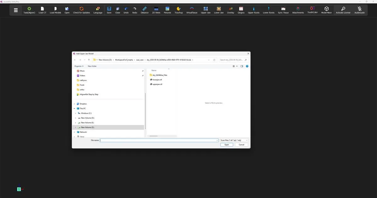
GuideMia then asks for the scans, one at a time, and the order matters:

Create a project with optical scan files but no CBCT scan. Select the upper jaw scan first. The lower jaw scan must be in an articulated position of the upper jaw scan.

Select the upper jaw scan first. The lower scan must already sit in an articulated position relative to the upper — GuideMia is not going to articulate them for you at this stage, and every occlusal judgement it makes from here on assumes the bite you hand it is the bite the patient has.

Scans can be STL, PLY or OBJ.

The file selection dialog, with the upper jaw scan chosen first. The file selection dialog, with the upper jaw scan chosen first.
Confirming the pair

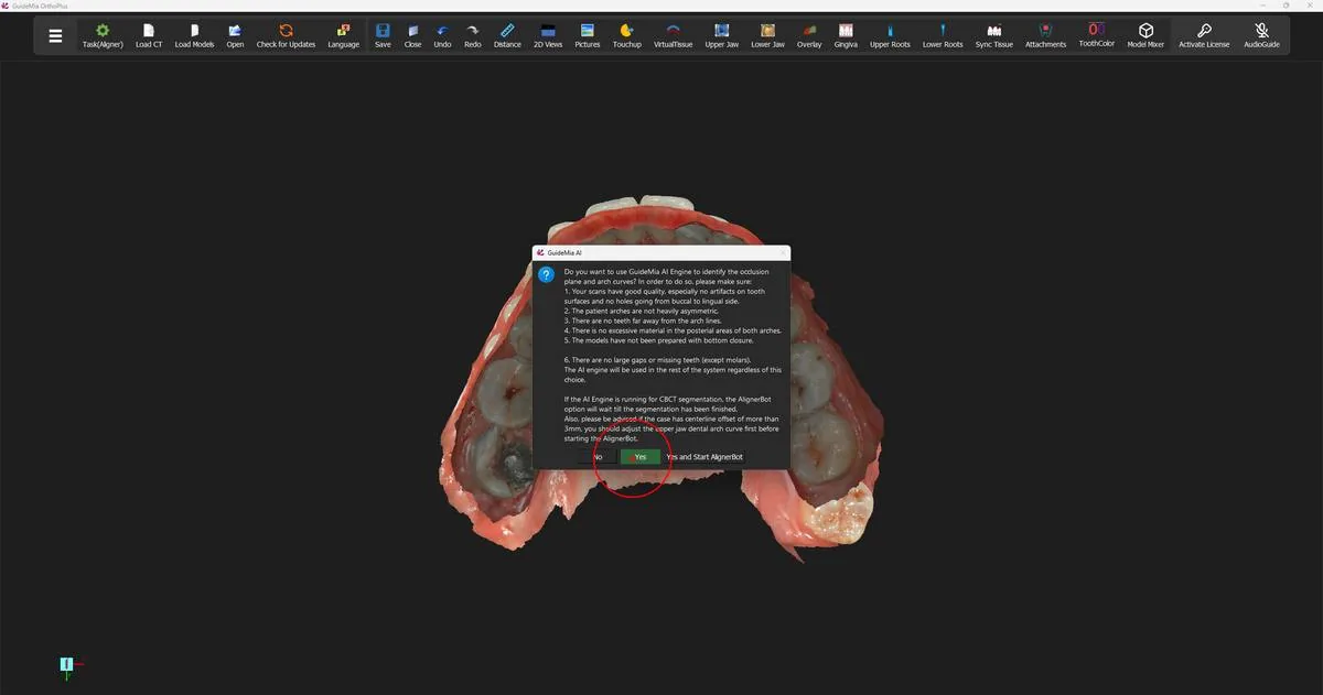
Once both scans are loaded GuideMia asks you to confirm before it commits them to the project. Answer Yes and the two arches appear together in the 3D window, in occlusion.

This is the first moment worth stopping at. Look at the pair from the front and from the side. If the arches interpenetrate badly, or sit apart, or one is rotated relative to the other, the articulation in the scan files is wrong — and it is far cheaper to fix that now, in your scanning software, than to discover it during movement planning six steps from now.

Both arches loaded and in occlusion, ready for the workflow to begin. Both arches loaded and in occlusion, ready for the workflow to begin.
Where you are now

The project exists and holds two arches in their scanned bite. Nothing has been analysed yet — GuideMia has two surfaces and no idea where the occlusal plane lies or where one tooth ends and the next begins. Establishing the first of those is the next step.

More on this page

The demo loads a case and moves straight on. The Load Case Data section of the workflow panel carries more than the demo used:

ControlWhat it is for
"New Project without CT"An optical-scan case, as used here
"Add Optical Scan"Bring another scan into an existing project
"Add Impression Scan"Load a scan of an impression rather than a model
"Case Information"The case's stored details, including any earlier plans
"Switch to selected plan"Move between plans held against the same case

If your case does have a CBCT, this is where the workflow diverges: the project is created with the CT, and two further stages — loading and registering the radiographic data — sit between here and step 2. That path is not covered in this guide.

Step 2 of 13

Setting the occlusion plane

Let the AI Engine propose the datum plane, then judge its orientation and midline — the reference every later measurement and the final centreline are built on.

Two scans in a shared bite are not yet a case. GuideMia has no idea which way is up, where the midline runs, or what "level" means for this patient. The occlusion plane — the datum plane — is what supplies all three, and it is the first thing the workflow builds.

It is worth understanding how far its influence reaches, because it is easy to treat this as a formality and click past it. The plane is the reference every later measurement is taken against: the arch curves are laid out on it, the angle between it and the FH plane is reported from it, and its centreline becomes the centreline the finished alignment is built around. GuideMia says so plainly in its own guidance for this step — "The centerline of the plane will determine the final centerline of the alignment, so it may not necessarily be the current center line of the upper jaw." If the plane is tilted or its midline is off, nothing downstream corrects it; it simply carries through.

Letting the AI engine propose the plane

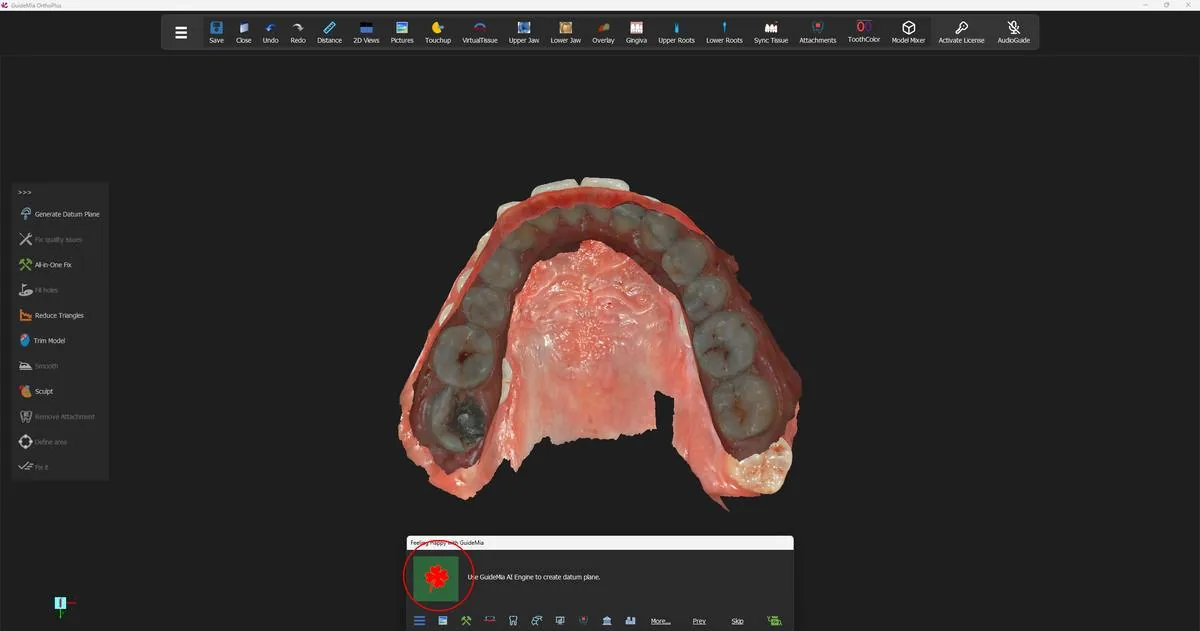
The Happy Button now reads Occlusion Plane, with a one-line instruction:

Use GuideMia AI Engine to create datum plane.

Press it. GuideMia analyses the upper jaw scan and produces the plane together with the control points the arch curves will be built from. This is the first point in the workflow that depends on the AI engine. Where the engine is not available you build the plane by hand instead, from four points: two on the lingual surfaces of the upper incisors, on the midline and at roughly the height the lower incisors will meet them, and two more at the centres of the occlusal surfaces of the molars or the area behind them. Generate Datum Plane on the tool bar to the left of the 3D view is the manual route.

The upper jaw alone, with the Happy Button standing on the occlusion plane step. The upper jaw alone, with the Happy Button standing on the occlusion plane step.
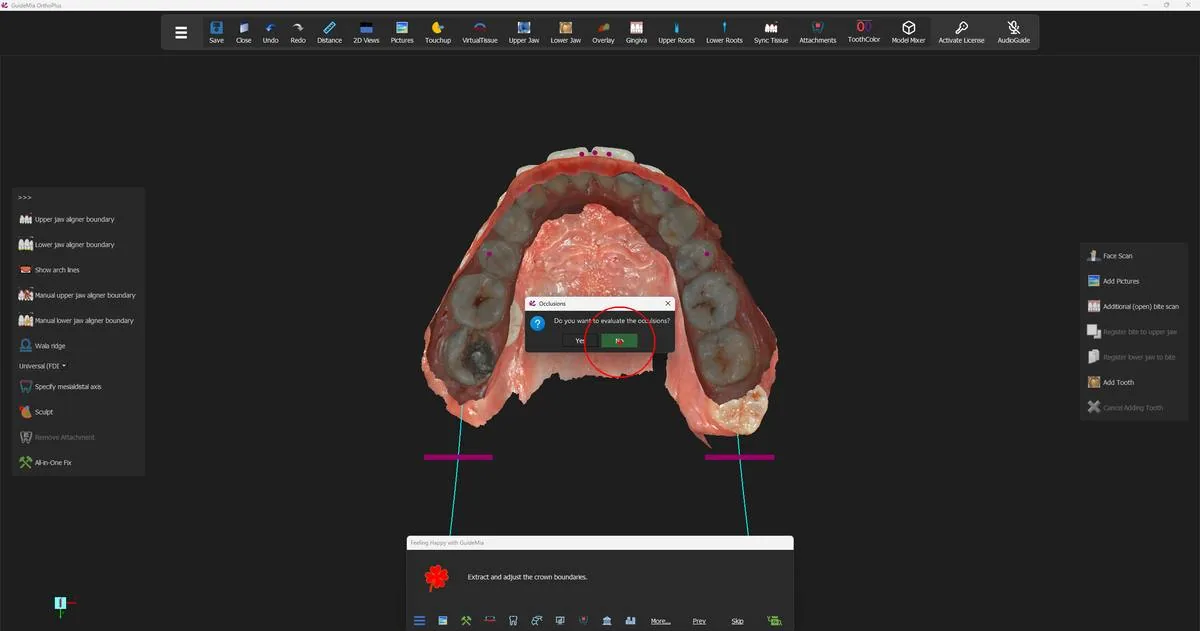
While the analysis runs, GuideMia asks a question of its own:

Occlusions — Do you want to evaluate the occlusions?

This case answers No, and carries on. The evaluation is not something you lose by declining: the occlusal distance map is available from the model's context menu at any point later in the case, and step 7 covers reading it. Answer Yes if you want to look at the bite as it came in before anything is changed.

GuideMia offering to evaluate the occlusions before the plane is settled. GuideMia offering to evaluate the occlusions before the plane is settled.
Reviewing what it produced

The Happy Button now reads Adjust occlusion plane, and its instruction is the real guidance of this step:

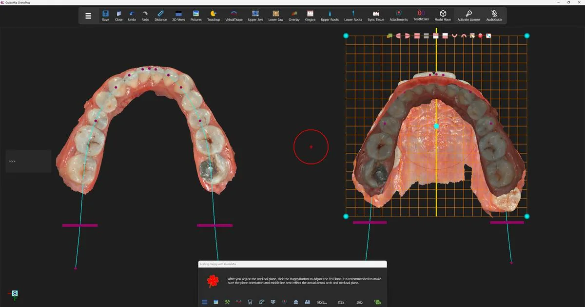
After you adjust the occlusal plane, click the HappyButton to Adjust the FH Plane. It is recommended to make sure the plane orientation and middle line best reflect the actual dental arch and occlusal plane.

Two things are on screen. In the working window on the left the upper arch is shown from the occlusal, overlaid with the arch control points and the arch curves GuideMia has derived. In the assembly window on the right the plane itself is drawn as an orange grid through the model, with a yellow centreline running front to back and round cyan handles at its corners.

The proposed plane in the assembly window, with its centreline and corner handles, and the arch control points on the model at left. The proposed plane in the assembly window, with its centreline and corner handles, and the arch control points on the model at left.
Judge two things, in this order.

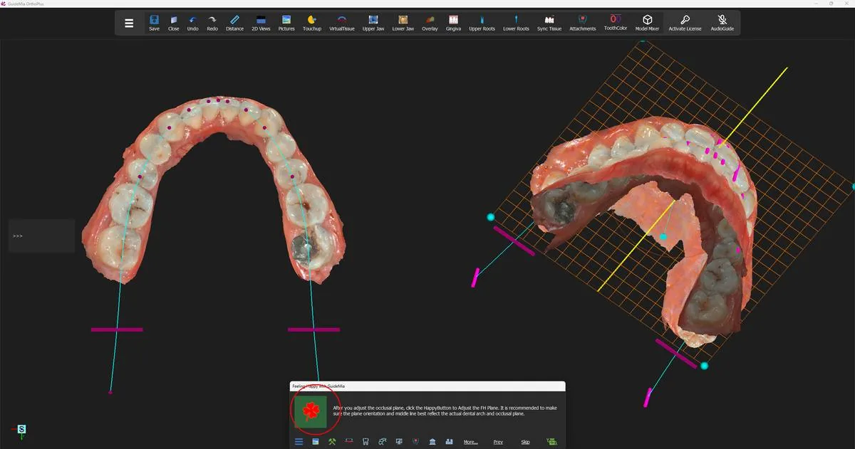
Orientation. Looking at the arch from the front, the plane should sit level across the arch rather than cant to one side; looking from the side, it should follow the occlusal surfaces rather than dive through them at the back. The grid makes this easy to read once you turn the model — where the grid stops being parallel to the run of the cusps, the plane is wrong. Turning the model is the step here, not an aside: the tilt that is invisible from the occlusal view is obvious from an oblique one.

The same plane seen obliquely, where a cant that the occlusal view hides becomes visible. The same plane seen obliquely, where a cant that the occlusal view hides becomes visible.
Midline. The yellow centreline is the one that matters. Set it where the patient's arch midline should be, which is not necessarily where the scanned upper arch's midline currently is — a displaced upper midline that you intend to correct should not be baked into the datum. Drag the handles until both readings are right.

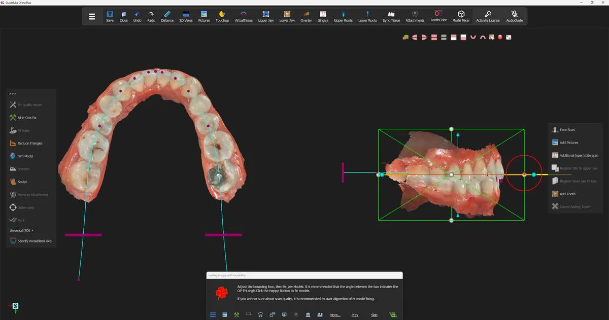
When they are, press the Happy Button again. GuideMia moves on to adjusting the FH plane, and a green bounding box appears around the models in the assembly window. That box, and what the angle between it and the occlusal plane means, is step 3.

Pressing on has produced the bounding box, and the instruction has changed to the model-fixing step. Pressing on has produced the bounding box, and the instruction has changed to the model-fixing step.
Opening the full workflow panel

Up to this point the tools you have needed have been placed in front of you, in the floating bars down each side of the 3D view. Those bars are rebuilt at every Happy Button step and carry only what that step needs — which is exactly right while the wizard is leading, and not enough when you want to do something it has not offered.

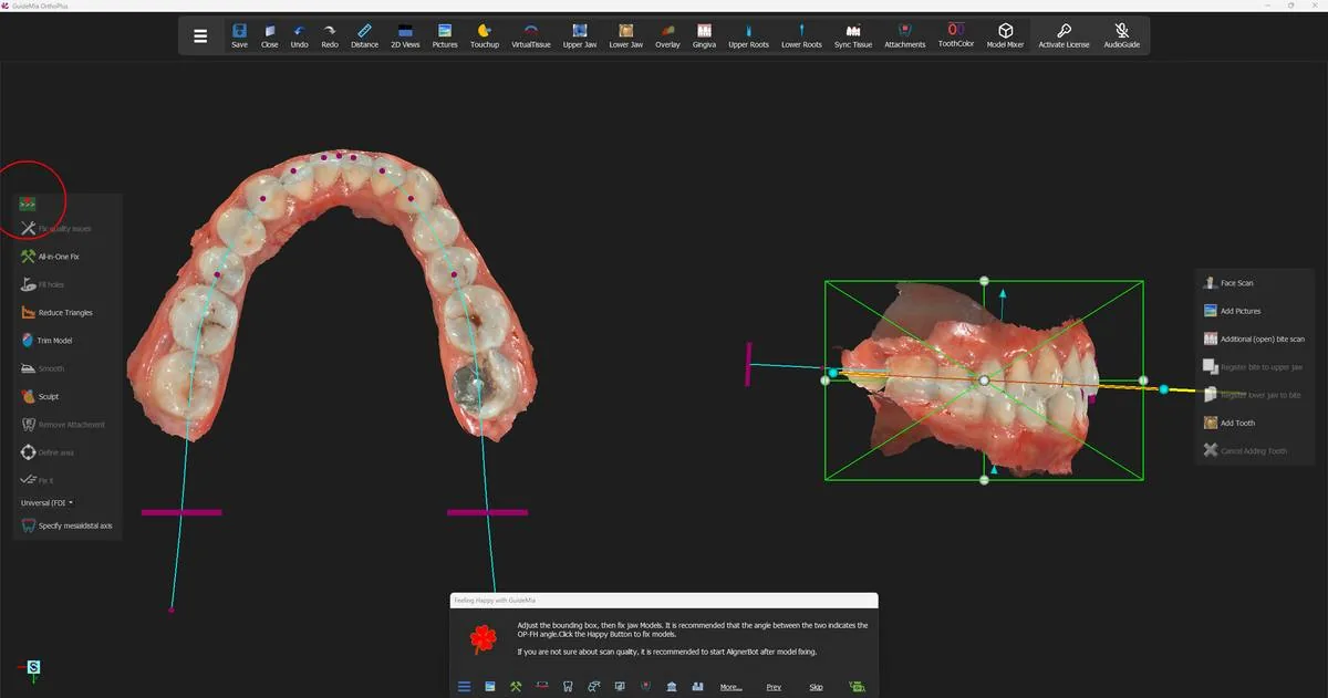
The ">>>" control at the top of the left-hand bar is the way out of that. Its status tip:

Turn on the full workflow panel and access more functions.

Press it and the full workflow panel becomes available, with a page for each stage of the case and every tool that stage owns. The panel and the floating bars are alternatives rather than companions — while the panel is up the bars stay suppressed, and closing the panel brings them and the Happy Button back. From here on, whenever this guide says a tool is "on the workflow panel", this is the control that gets you there.

The ">>>" control at the head of the left-hand tool bar. The ">>>" control at the head of the left-hand tool bar.
Where you are now

The case has a datum plane, an orientation and a midline, and GuideMia has derived a first set of arch control points from them. The scans themselves have not been touched yet — no holes filled, no artefacts removed, no bottoms closed. Repairing them is the next step.

More on this page

While the occlusion-plane steps are current, the left-hand bar carries the model-fixing set. None of it was needed on this case, but it is the right place to deal with an obviously bad scan before the plane is committed:

ControlWhat it is for
"Generate Datum Plane"Build the plane from four hand-placed points, when the AI engine has not produced one
"Fix quality issues"Bring up the model-fixing tools for the current model
"All-in-One Fix"Geometry and topology repair in one pass, including holes that connect the buccal and lingual sides
"Fill holes"Close openings left by an incomplete scan
"Reduce Triangles"Thin a mesh that is heavier than it needs to be
"Trim Model"Cut the model back to a boundary
"Smooth"Even out a rough surface
"Sculpt"Push and pull the surface by hand
"Remove Attachment"Take an existing attachment off the scan
"Define area" / "Fix it"Mark a region and repair only that region

On a case that does have a CBCT, this step also offers the volume-circling tools; that path is not covered in this guide.

Step 3 of 13

Fixing the jaw models

Set the bounding box that reports the OP-FH angle, read the scan-quality report, choose how hard to repair, and inspect the result — the step everything else inherits.

An intra-oral scan is a surface, and surfaces arrive with defects: holes where the scanner could not see, spikes and bubbles from a plaster model, triangles whose normals point the wrong way, thin bridges of geometry connecting the buccal and lingual sides through an interproximal space. None of that stops you looking at the model. All of it stops the operations that come next — crown boundaries cannot be traced reliably across a hole, teeth cannot be lifted cleanly out of a non-manifold mesh, and a model with inconsistent normals cannot be closed into a solid.

This step is one Happy Button press. It is also the heaviest single press in the workflow, and it is the last comfortable moment to deal with a scan you are not happy with.

The bounding box, and the angle it reports

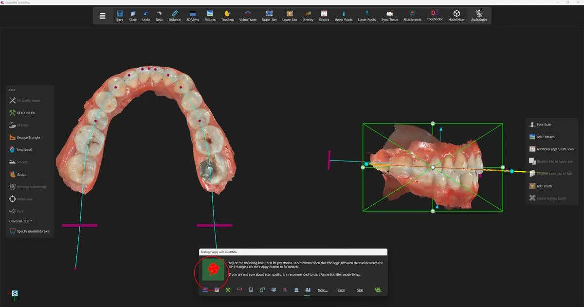
Before the repair, GuideMia puts a green bounding box around the models in the assembly window and asks you to set it. Its instruction:

Adjust the bounding box, then fix jaw Models. It is recommended that the angle between the two indicates the OP-FH angle. Click the Happy Button to fix models.

The step's full title spells out what the box is and is not:

Adjust the bounding box, then fix jaw Models. This is only to adjust view orientation but not the occlusal plane. Rotations about the Z or Y axis indicates the FH plane and the occlusal plane have corresponding discrepancies.. [sic]

Read that carefully, because the box looks like a manipulator and is not one. Turning it does not move the occlusal plane you settled in step 2 and does not move the models — it sets the orientation the case is viewed and framed in, which GuideMia treats as the FH plane. The consequence is the useful part: once the box represents FH and the plane represents the occlusion, the angle between them is the OP-FH angle, and you have it as a by-product of setting up the view. If you find yourself rotating the box about Z or Y to make it look right, that rotation is telling you the two planes disagree by that much.

The bounding box on the models in the assembly window, with the occlusal plane still drawn through them. The bounding box on the models in the assembly window, with the occlusal plane still drawn through them.
The instruction carries a second paragraph on this case, because the scans are colour scans:

If you are not sure about scan quality, it is recommended to start AlignerBot after model fixing.

This is the first of the points where GuideMia offers to finish the case for you. AlignerBot presses the Happy Button step after step, without stopping, to the end of the design. The advice being given is about where to hand over: let the model repair happen under your eye, look at the result, and start the automatic run from there rather than from a scan you have not inspected. The repair is the step whose outcome everything else inherits.

What GuideMia tells you about the scan

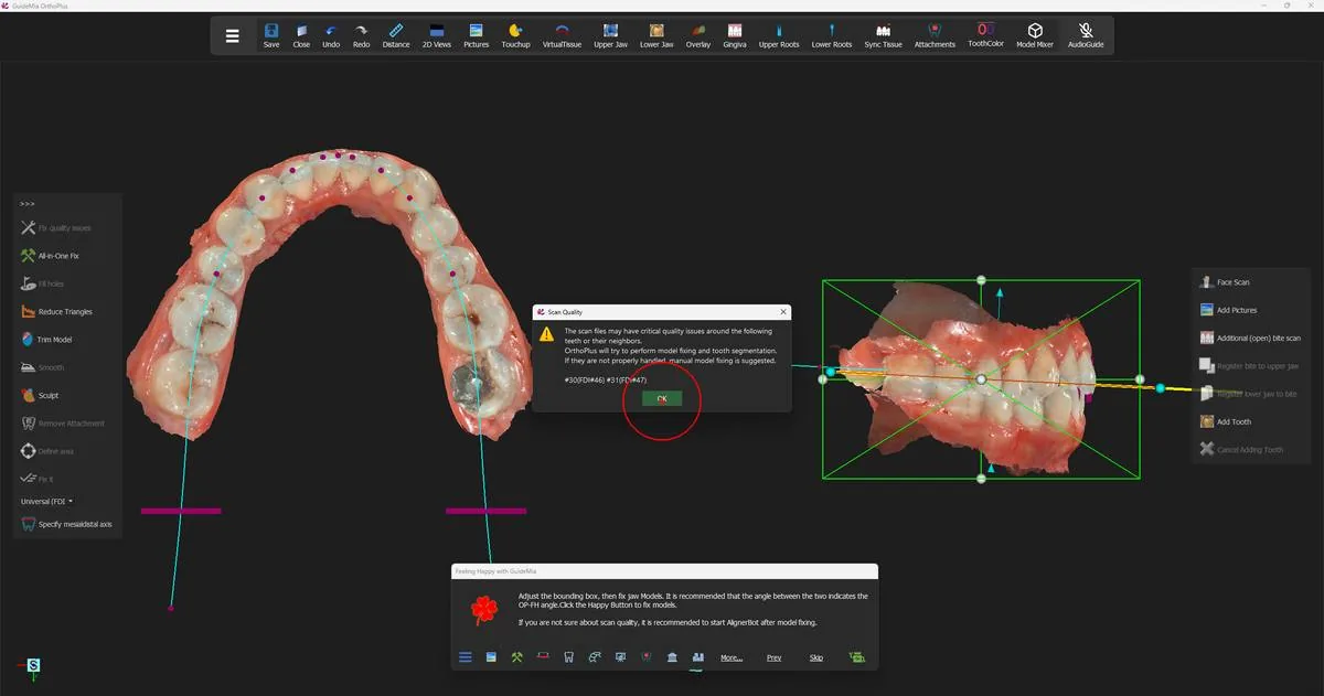
Press the Happy Button and, before anything is repaired, GuideMia reports what it has found:

Scan Quality — The scan files may have critical quality issues around the following teeth or their neighbors. OrthoPlus will try to perform model fixing and tooth segmentation. If they are not properly handled, manual model fixing is suggested. #30(FDI#46) #31(FDI#47)

Note what this is and what it is not. It is not a refusal, and it is not a prediction of failure — GuideMia will go ahead and try. It is a list of the teeth to look at afterwards. On this case they are the lower right first and second molars, and the numbering is given twice — once in the Universal scheme and once, in brackets, in FDI — so that whichever you read, you know which teeth are meant.

Write the numbers down. They are the teeth whose crown boundaries you will check first in step 4, and the teeth whose segmentation you will check first in step 5. OK dismisses the dialog.

The scan-quality report, naming the teeth that need watching. The scan-quality report, naming the teeth that need watching.
Choosing how hard to repair

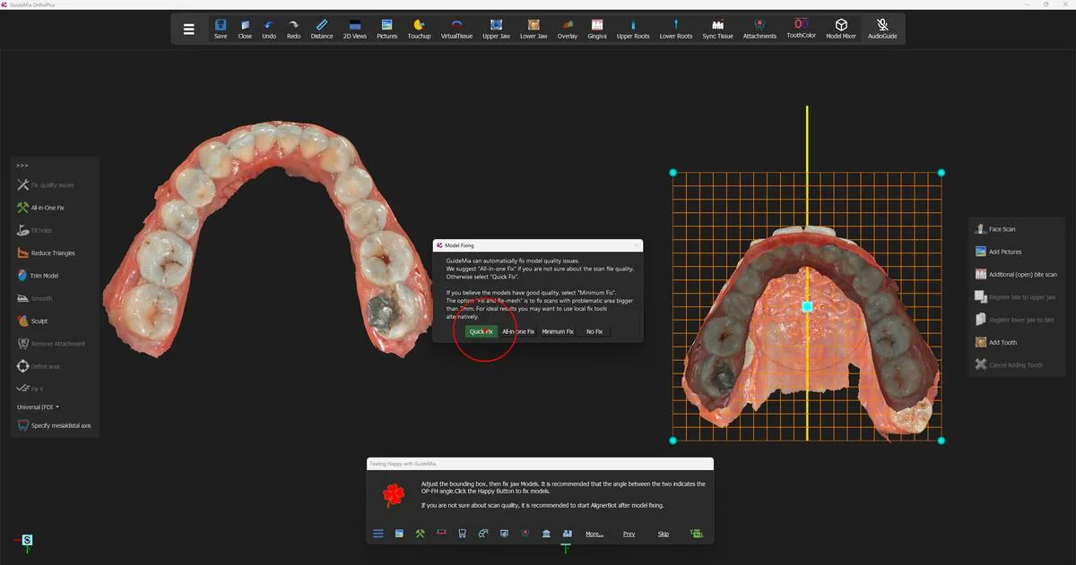
GuideMia then asks which repair to run:

GuideMia can automatically fix model quality issues. We suggest "All-in-one Fix" if you are not sure about the scan file quality. Otherwise select "Quick Fix". If you believe the models have good quality, select "Minimum Fix". The option "Fix and Re-mesh" is to fix scans with problematic area bigger than 2mm. For ideal results you may want to use local fix tools alternatively.

The buttons are "Quick Fix", "All-in-one Fix", "Minimum Fix" and "No Fix". Read the advice as a scale keyed to how much you trust the scan: "All-in-one Fix" when you are not sure of it, "Quick Fix" when you are, "Minimum Fix" when you believe the models are already good. "Fix and Re-mesh" is reserved for damage larger than 2 mm — and note that even there the advice points you at the local fix tools instead if you want the best result.

This case takes "Quick Fix" — two flagged molars on an otherwise clean pair of colour scans.

The repair options, with the models behind them. The repair options, with the models behind them.
One thing worth knowing if you later reach for the same repair by hand: the all-in-one fix run from this step is not quite the button of the same name on the workflow panel. The version the Happy Button runs can use the arch curve information to guide the repair, and the panel version cannot. If a manual repair seems to do less than the wizard's did, that is why.

After the repair

GuideMia removes the large flat triangles from the bottoms of the jaw models, repairs both models, and then aims the working window at each jaw in turn so you can look at the result. Use that: turn each model and check the areas the scan-quality dialog named, and check anywhere the scan was thin at the gingival margin.

If you are not satisfied, the whole repair toolbox is on the workflow panel's data-processing page — including the tools for the specific problems the wizard does not target, such as plaster-model bubbles and an over-long model boundary. GuideMia's own advice is to do that work there and then come back to this step for a final pass, rather than to fight it here.

Both models repaired, with the Happy Button now offering crown boundaries. Both models repaired, with the Happy Button now offering crown boundaries.

Where you are now

Both jaw models are repaired and oriented, and you know which two teeth on this case are likely to give trouble. The models are still open surfaces, and GuideMia still has no idea where one crown ends and the next begins. Finding the crowns, and closing the models into solids, is the next step.

More on this page

The repair is one press, but the "Data Processing" section of the workflow panel's data-preparation page carries a great deal more, and this is the stage to use it:

ControlWhat it is for
"Mesh Optimization"Refine and reduce triangles, and remove non-manifold geometry
"Smart Fix"Repair by normal consistency — reversed triangles, non-manifold edges
"All-in-One Fix"The heavy repair, run on its own
"Plaster Model Scan Cleanup"Smooth away bubbles and small artefacts typical of a plaster scan
The bubble-size boxThe rough radius of the bubbles the cleanup will act on
"Reduce Undercuts According to View Direction"Reduce, not block out, undercuts on the current model — full block-out would make aligners too loose
"Track boundary"Click points on the model to define a contour; click the first point again to close it
"Cut Model Base"Trim the current model with that contour
"Reverse Cut"Keep the other side of the cut instead
"Automatic boundary cleanup"Tidy the model boundary — needs crown boundaries to exist first, so it belongs after step 4
"Add Tooth" / "Cancel Adding Tooth"Place a virtual tooth into a gap, sized and oriented by its bounding box
"Align models and CT"The only route to the registration tool; CBCT cases only

Two of these are worth a caution. "Track boundary" and "Add Tooth" are both toggles — you click the same button again to finish — and while either is active, moving the mouse off the model is how you rotate the view without adding a point. A right-click, or Escape, abandons what you were drawing.

Step 4 of 13

Crown boundaries and base models

Trace the crown boundaries the segmentation will follow and close the open scans into solid base models.

Two things happen in this step, and although the Happy Button runs them as one continuous sequence they answer different questions.

The crown boundaries answer where the teeth are. GuideMia traces the line where each crown meets the gingiva, and merges those individual loops into one continuous curve per arch. The software calls that merged curve the aligner boundary — the name refers to the merging, not to the individual crowns — and you will see both terms. It is the input tooth segmentation depends on: step 5 does not find the teeth from scratch, it cuts along boundaries that are decided here.

The base models answer what the arch is made of. The scans are open surfaces, and an aligner cannot be formed on an open surface any more than an arch model can be printed from one. Base models are the closed, solid arch models everything downstream is manufactured from — trimmed back to the aligner boundary, extended, and closed underneath.

Extracting the boundaries

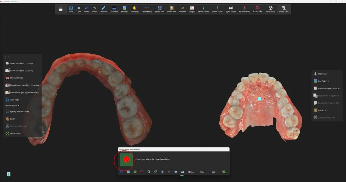
The Happy Button reads Crown Boundaries:

Extract and adjust the crown boundaries.

Before pressing it, the operator turns the occlusal distance map off from the model's context menu, so the model is shown in its own colours rather than under a contact-shaded overlay. The display toggles are covered in step 7; the habit is worth adopting now, because every judgement in this step is a judgement about a line on a surface, and a colour map over the surface makes the line harder to read.

Pressing extracts the aligner boundary on both jaws in one go and looks down at the arches from above. What you get is a violet loop running round every crown on both arches.

Both arches with the aligner boundary extracted — one continuous loop per jaw, following the gingival margin of every crown. Both arches with the aligner boundary extracted — one continuous loop per jaw, following the gingival margin of every crown.
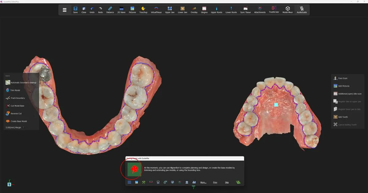
Check the boundary before you go on, and check the teeth the scan-quality dialog named first. The boundary is dragged anywhere along its length to correct it — you do not have to redraw a segment to move it. Look for the loop running up onto a crown where the gingival margin is indistinct, and for it dropping down into the gingiva where the scan is thin.

What GuideMia wants from the arch curves

The boundary is derived with the help of the arch curves, and this is where the work you put in pays off later. GuideMia's own explanation of what a good arch curve looks like is the most useful passage in the wizard:

Adjust the curves so that they follow the shape of the dental arches. It is suggested to make sure that for each of the teeth, if there are interproximal areas on both mesial and distal side, imagine a line connect the two sides. Make sure the arch curves follow such a line for each of the teeth. This will help segmentation. The curves don't have to pass or be over the teeth, but should follow this direction.

So the curve is not a cosmetic outline of the arch. Through each tooth it should run in the direction of that tooth's own mesial-to-distal line. A curve that sweeps smoothly past a tooth which is itself rotated out of the arch is a curve that will mislead the segmentation.

Three specific cases are worth knowing before you meet them:

  • The range bars. Two short horizontal bars sit on each arch curve. They set the range that will be segmented. Move them so they sit close to the last posterior teeth you intend to treat.
  • A missing tooth. Drag the curve so that its buccal and lingual sides meet in the middle of the gap. If you do not, GuideMia will treat the gap as tooth area and try to find a crown there.
  • A tooth completely out of the arch. Exclude it from the boundary curve altogether and segment it by hand later, rather than distorting the curve to reach it.

Building the base models

The Happy Button now reads Create Base Model, and takes two presses.

At this moment, you can use AlignerBot to complete planning and design, or create the base models by trimming and extending jaw models, or using the bounding box.

This is the second point at which GuideMia offers to finish the case on its own. AlignerBot from here would run the remaining steps — base models, segmentation, planning, staging and design — without stopping. Everything the rest of this guide describes is what it would be doing.

Press, and GuideMia trims the model boundaries back to the extracted aligner boundary and builds the upper base model. The margin box on the tool bar, set to 5.00(mm), is the distance it leaves between the model boundary and the crown boundaries.

The first press of Create Base Model, with the trimming tools and the margin box on the bar at left. The first press of Create Base Model, with the trimming tools and the margin box on the bar at left.
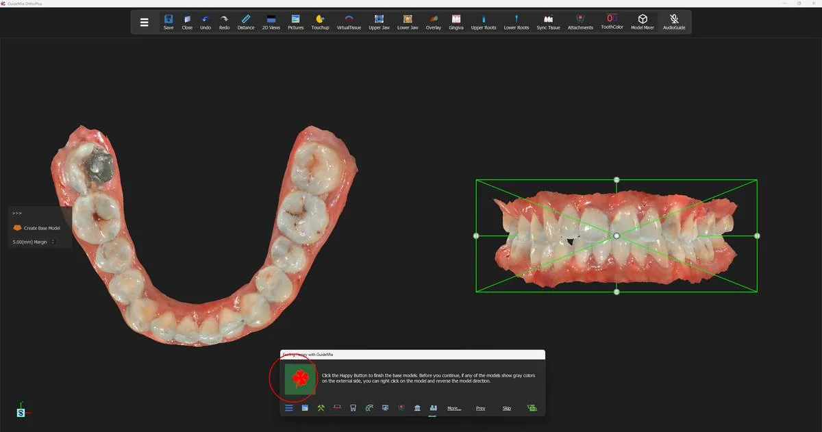
The automatic trim is honest about its own limits:

The automatic trimming may not generate ideal models. It may have excessive materials if the original scans are not ideal.

If a model comes out with more material than you want, right-click it to make it current and use the trimming tools — "Track boundary" to draw the line and "Cut Model Base" to cut to it — before pressing on.

The grey side

The second press finishes the models, and its instruction carries a warning that you must act on rather than read past:

Click the Happy Button to finish the base models. Before you continue, if any of the models show gray colors on the external side, you can right click on the model and reverse the model direction.

Grey on the outside of a model means the surface is facing inwards — its normals are reversed. GuideMia does not correct this for you, and it is not cosmetic: a model whose outside is its inside cannot be closed into a valid solid, and everything built on that solid inherits the fault.

So before pressing: turn both models and look at them from outside. If either reads grey where it should read like a surface, right-click it and reverse the model direction, and only then press.

The second press, with the lower base model closed at left and both arches boxed in the assembly window at right. The second press, with the lower base model closed at left and both arches boxed in the assembly window at right.
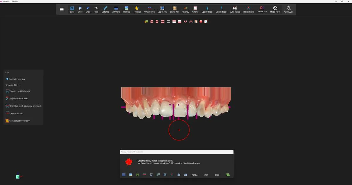
Pressing finishes the lower base model and moves the workflow on to tooth segmentation.

One thing to file away for later. You are not locked out of this step once you leave it. GuideMia is explicit that you can come back at any point in the workflow — even after treatment planning — regenerate the arch models if they turn out to be too short for aligner manufacturing, and then use Sync Tissue on the toolbar to re-segment the teeth. The tooth setup and movement plans are reapplied to the new models automatically.

The finished base models, with the workflow now standing on tooth segmentation. The finished base models, with the workflow now standing on tooth segmentation.
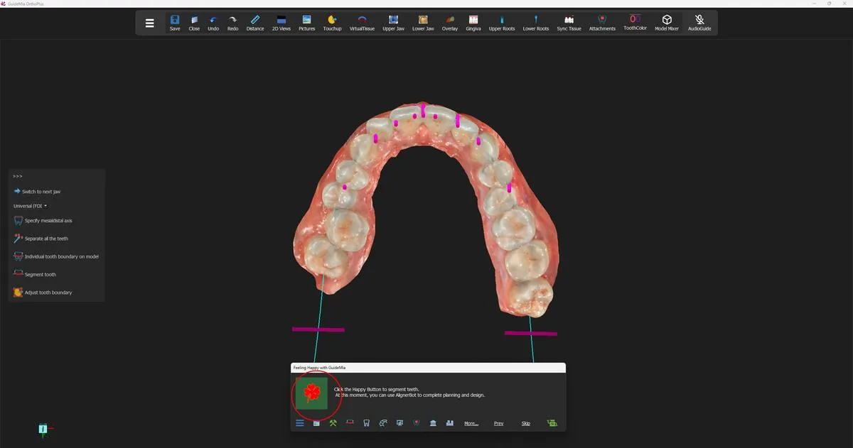
Where you are now

Both arches are closed solid models, trimmed to a boundary that follows the crowns, and each arch carries a continuous aligner boundary and an arch curve that describes the run of its teeth. That is everything tooth segmentation needs as input. It is still one object per arch — the teeth do not exist yet as things you can move. That is the next step.

More on this page

The "Arch and boundaries" section of the workflow panel's data-preparation page owns the boundary work, and the "Base Model" tools sit on the data processing section beside it:

ControlWhat it is for
"Show arch lines"Show and adjust the arch curves the boundary tools work from
"Upper jaw aligner boundary"Extract the upper crown boundary as one merged loop
"Lower jaw aligner boundary"The same for the lower arch
"Manual upper jaw aligner boundary"Draw the upper boundary by hand, point by point, closing on the first point
"Manual lower jaw aligner boundary"The same for the lower arch
"Wala ridge"Mark the Wala ridge on the lower arch
"Automatic boundary cleanup"Tidy the model boundary; needs the crown boundaries to exist first
"Create Base Model"Build the closed arch models on their own, outside the wizard
The margin boxDistance from the model boundary to the crown boundaries; 5.00(mm) here
"Trim Model" / "Track boundary" / "Cut Model Base" / "Reverse Cut"Trim a model back by hand before closing it

Two asymmetries in that list catch people out. The manual upper boundary is drawn in the assembly window on the right; the manual lower boundary is drawn in the working-object window on the left, and if the lower jaw is not showing there you right-click it in the assembly window to make it current first. And the "Create Base Model" button in the panel is not quite the one the Happy Button pressed — the wizard's version uses the extracted crown boundaries to trim the jaw models automatically before closing them, and the panel's version gives you a bounding box to size by hand instead.

Step 5 of 13

Segmenting the teeth

Separate every tooth from the arch with the AI Engine, check the flagged teeth first, and correct a boundary by hand where needed.

Everything you will plan from step 6 onwards is applied to an individual tooth. A movement, an attachment, an IPR value, a step in the staging table — each of them names a tooth and acts on it. So far no tooth exists. Each arch is one solid model with a boundary drawn on it, and the boundary is a line on a surface, not a cut through it.

Segmentation is where GuideMia makes the cut: it lifts each crown off the arch, gives it a number, works out which way it is oriented, and builds a root under it. It runs once for the upper jaw and once for the lower, and it takes seven presses of the Happy Button to get through both. This step walks all seven, because they are not repetitions of one another — the two jaws are interleaved, and the presses in between do work you should look at before allowing the next one.

This is also the third and last point at which GuideMia offers to take over. Pressing AlignerBot here runs the segmentation, the planning and the design without stopping. Read the step even if you intend to use it; when a case does need a hand, these are the tools.

Giving the difficult teeth a direction

The Happy Button reads "Tooth Medisaldistal Direction" [sic], and the view swings underneath the upper arch so you are looking at its occlusal surfaces.

Click the Happy Button to segment teeth. At this moment, you can use AlignerBot to complete planning and design.

The step is named after work that is optional, and the message does not mention it, so it is easy to press straight through. Before you do, consider whether this case wants any axes drawn. GuideMia's own rule for when it matters:

This is optional if the tooth arrangement is not too bad. For the teeth that are way off the arch curve, or the teeth that have very big rotation angle, it is recommended to draw the mesial distal axis in order to assure the segmentation will succeed.

Turn on "Specify mesialdistal axis", pick the tooth in the tooth-number control beside it, and draw across the tooth the way you would place a distance measurement. The direction is not the same for the two jaws: on the upper jaw draw from the patient's right to left, and on the lower jaw from left to right. The axis you draw is the direction GuideMia works from, so check which jaw you are on before you draw.

The tooth-number control shows both numbering schemes at once — the Universal number, with the FDI number in brackets — and it arrives preset to tooth 2 (FDI 17), the upper right second molar, ready for you to work forward along the arch. Leave it alone and GuideMia segments every tooth and assigns the numbers itself.

The upper arch from below, ready for mesial-distal axes; the short magenta bars are the axes already recognised. The upper arch from below, ready for mesial-distal axes; the short magenta bars are the axes already recognised.
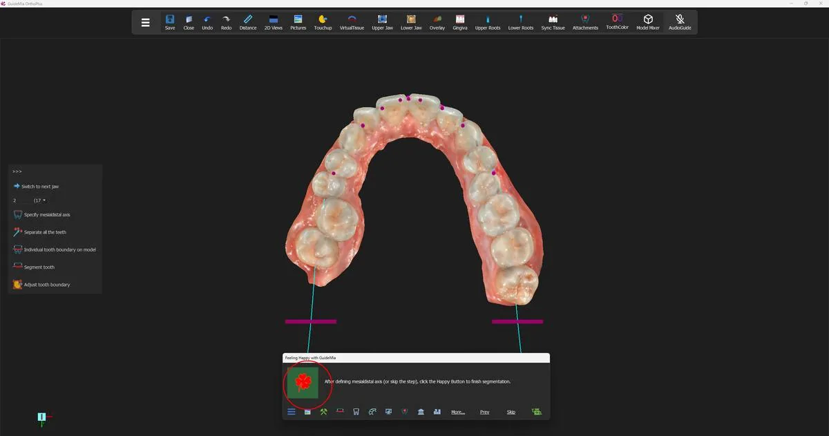
This case needs none drawn. Press.

Separating the teeth

The Happy Button now reads Tooth Segmentation:

After defining mesialdistal axis (or skip the step), click the Happy Button to finish segmentation.

The tooth-number control preset to tooth 2 (FDI 17), with the segmentation about to run on the upper arch. The tooth-number control preset to tooth 2 (FDI 17), with the segmentation about to run on the upper arch.
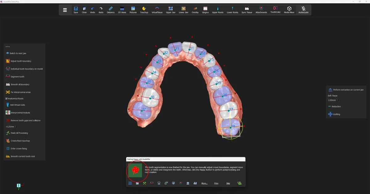
Pressing runs the whole upper arch at once. It is not a single sweep across the teeth: GuideMia "may try a couple of times for each tooth, and may run more than one rounds for the entire jaw". Give it time to finish rather than assuming it has stalled. It is also the step most sensitive to scan quality — which is why step 3 asked you to write down the teeth the scan-quality report named.

The upper arch separated: each crown its own object, numbered, in alternating colours, with its axes drawn on it. The upper arch separated: each crown its own object, numbered, in alternating colours, with its axes drawn on it.
The teeth come back in alternating shades. That is "Toggle teeth", on by default, and it exists so that two adjacent boundaries can be told apart at a glance. The numbers drawn on the crowns are FDI.

Judging the result

The Happy Button now reads Post Processing, and this is the decision point of the step:

The tooth segmentation is now finished for the jaw. You can manually adjust crown boundaries, segment more teeth, or delete and resegment the teeth. Otherwise, click the Happy Button to perform postprocessing and root creation.

Look at the arch before you accept it. Three faults are worth hunting for: a tooth that was not segmented at all, a boundary that has cut up into the gingiva or across into the neighbour, and a crown that has come away carrying part of something else. Turn the model and look from the buccal and the lingual as well as from the occlusal — a boundary that looks right from above is often the one that has run too far down an interproximal space.

If something is wrong, fix it here. It is far cheaper than discovering it during movement planning:

  • Adjust a boundary that is close but wrong with "Adjust tooth boundary". It works on the current tooth, and it undoes any post-processing on that tooth first, shows you the boundary on an unsegmented surface, and lets you drag it.
  • Segment a tooth that was missed with "Individual tooth boundary on model", then "Segment tooth". Pick four to six points around the crown boundary, and do not pick any points in the interproximal area — that is the whole technique.
  • Delete and re-segment a tooth that came out badly enough that adjusting it is not worth the effort. Right-click the tooth model and delete it.
  • Fix a wrong number with "Change tooth number". Misnumbering happens on crowded arches and on arches with missing teeth, and it is worth checking now rather than reading a plan later that refers to the wrong tooth.

To work on a particular tooth you have to make it current, and the way you do that is not discoverable: in the assembly window, middle-click the blue arrow on the tooth. Five different tools depend on that gesture.

What the press actually does

Pressing at Post Processing runs three operations over the jaw and then a fourth. The three are boundary smoothing, tooth-orientation identification and interproximal repair — the same three the panel's "Fix all for the jaw" runs, each of which can also be run alone. The fourth is root creation.

Roots, and what they are on this case. GuideMia builds a body under every crown. With CBCT data it can follow the real anatomy. This case has no CBCT and no apical centres, so what it builds instead comes "according to statistical data" — a plausible root shape rather than a measured one. A checkbox, "Anatomical Roots", decides whether you get root-shaped bodies at all or simple pontics; its guidance is to turn it on when emerging teeth are present.

That distinction earns its place here because of what roots are used for. From step 6 onwards the roots are what collision detection reads when it decides whether two teeth will interfere as they travel. On a case built from statistics rather than radiographs, an interference warning is a well-informed estimate. Read it as one.

Checking the orientations

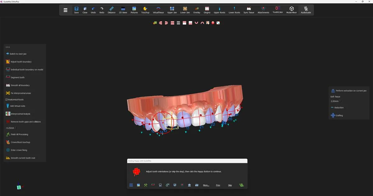
The Happy Button now reads Tooth Orientation:

Adjust tooth orientations (or skip the step), then click the Happy Button to continue.

Do not skip this one lightly. GuideMia is more insistent about tooth orientation than about anything else in the segmentation stage, and the reason is downstream:

It is very important to make sure the tooth orientations match the actual teeth. […] If the tooth orientation is not set right, the automatic tooth setup can place the tooth in a wrong position. Even though you can adjust tooth positions, the collision checking or IPR control can still produce less satisfactory results.

Each tooth carries three axes, drawn on it and colour-coded: blue is the vertical long axis, red is the buccal direction, green is mesial-distal. What you are checking is that the long axis really does run up the tooth and that the buccal arrow really does point buccally — on a rotated or tipped tooth those are exactly what the automatic pass is most likely to get wrong.

To correct one, middle-click its blue arrow. A bounding box appears around the tooth, and rotating the box rotates the orientation. If roots have already been created you will see the root update as you turn it.

Middle-clicking the blue arrow on a tooth brings up its bounding box and rotation handle. Middle-clicking the blue arrow on a tooth brings up its bounding box and rotation handle.
One property of the automatic orientation pass is worth knowing, because it looks like a bug and is not: "It can be a progressive process, so each time this function is executed, the resulted tooth orientations can be different." Running "Optimize tooth orientations" a second time and getting a different answer is expected behaviour, and "run it again" is a legitimate remedy when one tooth has come out wrong.

The lower jaw

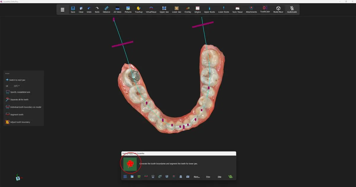
Pressing at Tooth Orientation switches to the lower jaw and presets the tooth-number control to tooth 18 (FDI 37). The Happy Button reads Tooth Boundary:

Generate the tooth boundaries and segment the teeth for lower jaw.

The lower arch, with the tooth-number control now at tooth 18 (FDI 37) and the arch curve and its range bars visible. The lower arch, with the tooth-number control now at tooth 18 (FDI 37) and the arch curve and its range bars visible.
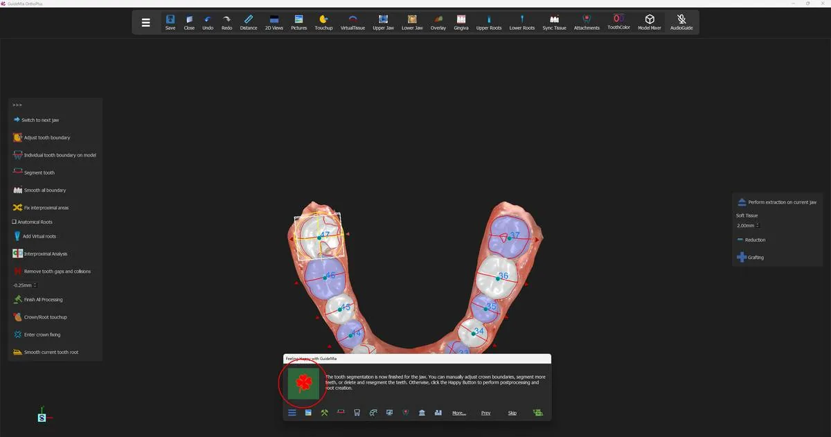
This press does for the lower arch what two presses did for the upper: it generates the boundaries and separates the teeth in one go. If you want to draw mesial-distal axes on the lower jaw, draw them before this press, and remember that the direction reverses — left to right on the lower jaw.

The Happy Button then reads Post Processing again, with the same message as before, and the same decision to make. GuideMia's guidance for this jaw is the most practical repair advice anywhere in the product, and it applies equally to the upper:

It is recommended that you inspect all the tooth boundaries and make necessary adjustment. Just right click on the tooth model you want to adjust, and select the menu item. If some teeth are not segmented, you can look for the manual segmentation tool on the left side of the workflow panel. […] Also please check the tooth numbers shown on the teeth. For some complex cases, the tooth numbers may not be right. If so, you can click right mouse button over a tooth, and select to change tooth number.

The lower arch segmented and numbered, ready for post-processing and roots. The lower arch segmented and numbered, ready for post-processing and roots.
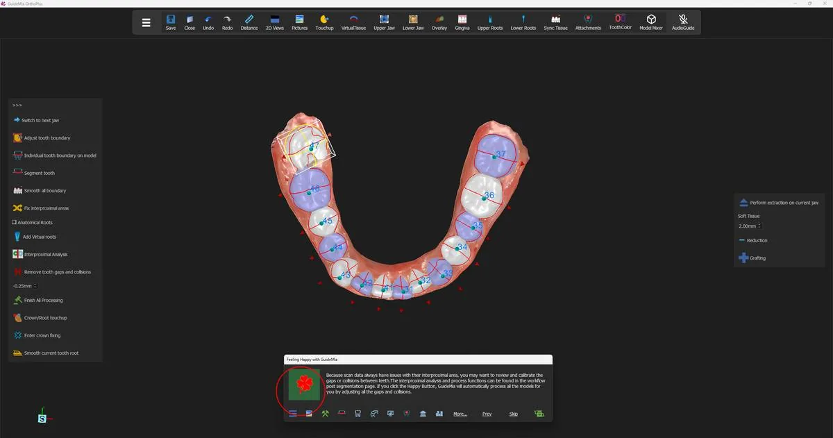
Press, and the lower jaw is smoothed, oriented, interproximally repaired and given its roots, exactly as the upper was.

Calibrating the contacts

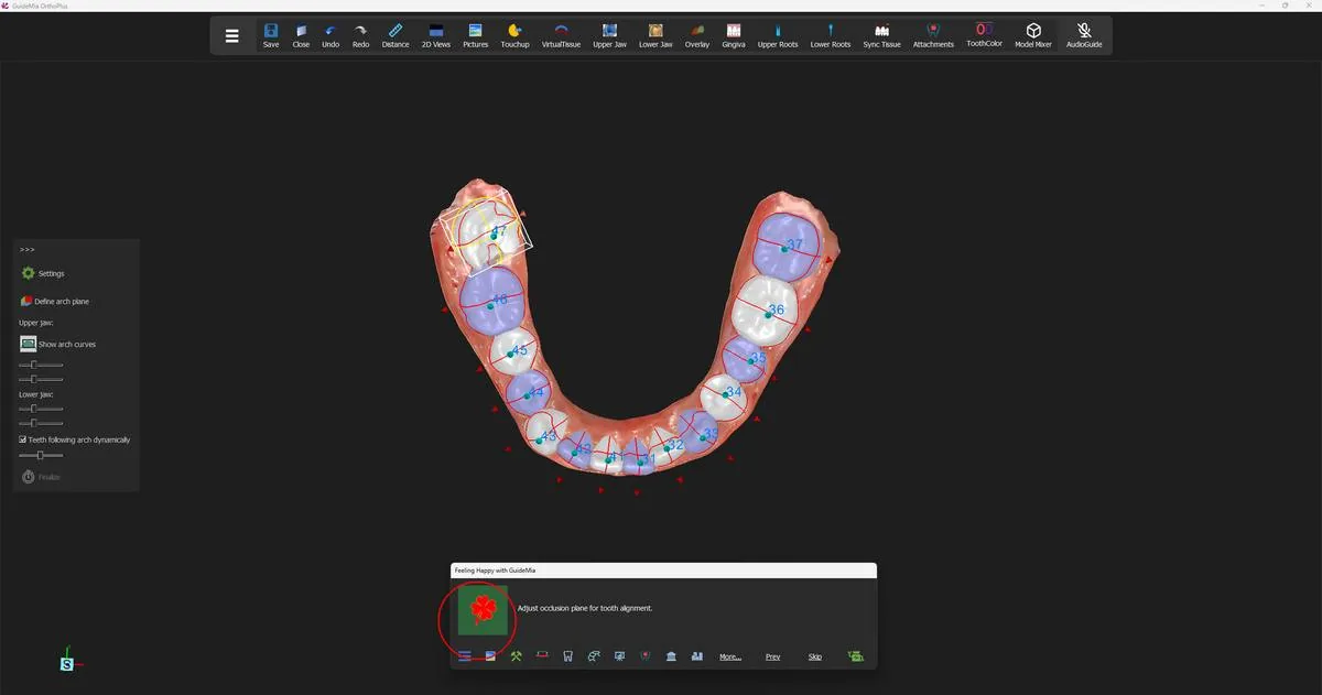
One press remains, and it exists because of how scanners behave rather than how GuideMia behaves. The Happy Button reads Interproximal Gap Calibration:

Because scan data always have issues with their interproximal area, you may want to review and calibrate the gaps or collisions between teeth. The interproximal analysis and process functions can be found in the workflow post segmentation page. If you click the Happy Button, GuideMia will automatically process all the models for you by adjusting all the gaps and collisions.

Where two teeth touch, a scanner cannot see into the contact and has to interpolate. What it leaves is either a small gap or a slight overlap, and neither is real. The blunt version is in the panel tool's own text: "the tooth segmentation represents the scan data but not the actual teeth." An overlap that is an artefact of scanning will be read by the movement simulation as a collision to be resolved, and a gap that is an artefact will be read as space that is available.

Press, and GuideMia works through both arches and closes them out — on this path it adjusts gaps and collisions within 0.2 mm. If you would rather inspect the contacts yourself first, "Interproximal Analysis" on the workflow panel turns the gap-and-collision display on, and right-clicking an individual interproximal area lets you calibrate just that contact instead of all of them.

The calibration step, with both arches fully segmented, numbered and rooted. The calibration step, with both arches fully segmented, numbered and rooted.
Where you are now

Both arches are separated into individual, numbered teeth. Each tooth has its three axes, a root beneath it, smoothed boundaries and repaired interproximal surfaces, and the contacts between teeth have been calibrated away from the scanner's guesses. Every tooth is now an object that can be moved, and the treatment plan begins in the next step.

More on this page

The workflow panel's tooth-segmentation page carries far more than the seven presses used. The demo touched almost none of it; a difficult case will need much of it.

Segmentation

ControlWhat it is for
"Switch to next jaw"Move segmentation to the other arch
"Tooth ID" and its dropdownSegment one numbered tooth instead of the whole arch
"Specify mesialdistal axis"Draw a tooth's direction to help a difficult segmentation
"Clear all"Remove every drawn axis and start again; delete any segmented teeth first
"Preview tooth boundaries"Show the likely crown divisions without segmenting — not a promise of the final result
"Toggle teeth"Alternating boundary colours; on by default
"Separate all the teeth"Run the segmentation for the current jaw — what the Happy Button presses
"Individual tooth boundary on model"Draw one tooth's boundary by hand: four to six points, none interproximal
"Segment tooth"Cut that tooth out along the drawn boundary
"Adjust tooth boundary"Re-open and drag the boundary of the current tooth
"Change tooth number"Correct a number GuideMia assigned wrongly
"Bolton Index:"A readout of the Bolton analysis

Post processing

ControlWhat it is for
"Fix all for the jaw"Smooth all boundaries, identify orientations and fix interproximal areas in one press
"Smooth all boundary"Boundary smoothing alone — possible to repeat, not recommended
"Optimize tooth orientations"Re-identify the axes; legitimately gives a different answer each run
"Fix interproximal areas"Fill patches into open interproximal surfaces; extends a little further each run
"Add Virtual roots"Build the roots on their own
"Anatomical Roots"Root shapes or simple pontics; turn on when emerging teeth are present
"Interproximal Analysis"Turn the gap-and-collision display on and off
"Remove tooth gaps and collisions"Calibrate every contact on the jaw; right-click a contact to do one at a time
"Finish All Processing"Run the whole finishing sequence in one go; it greys itself out afterwards
"Crown/Root touchup"Push or pull the surface of the current crown or root
"Enter crown fixing"Edit the crown boundary against the root; undoes interproximal fixing and smoothing
"Smooth current tooth root"Smooth one root a little per press
"Reduction" / "Grafting" and the millimetre boxReduce or add gum around the current tooth, for excessive gum, recession or emerging teeth
"Perform extraction on current jaw"Carry out planned extractions; tick the teeth on the tooth-extraction dock first
"Cancel extraction on current jaw"Undo the extractions on this jaw

The soft-tissue tools carry a safety statement in their own help text, and it is worth repeating verbatim: "It is advised that the final aligners need to be checked against the actual jaw model if you use the functions in this section to modify the teeth and tissue models."

Step 6 of 13

The first alignment

GuideMia's automatic setup: the arch curves, the proposed final positions, and how to read them before touching a tooth.

Everything so far has been preparation. The scans were loaded, the occlusal plane was established, the arches were cut into individual teeth and each tooth was given a root. None of that expressed any clinical intent — it described the patient as they are.

This step is where the case first says what it wants to become. Four presses of the Happy Button take GuideMia from a set of separated crowns to a complete proposed arrangement: every tooth moved onto an arch curve, collisions and interproximal contacts settled, attachments placed. It is the first time the case looks at itself, and it is the first result in the whole workflow that you have to judge rather than accept.

Take the judging seriously. An alignment that looks wrong here is almost never the alignment's fault — it is segmentation, or the articulation of the two scans, showing through. Both are far cheaper to fix now than after the case has been staged into aligners.

The occlusal plane, once more

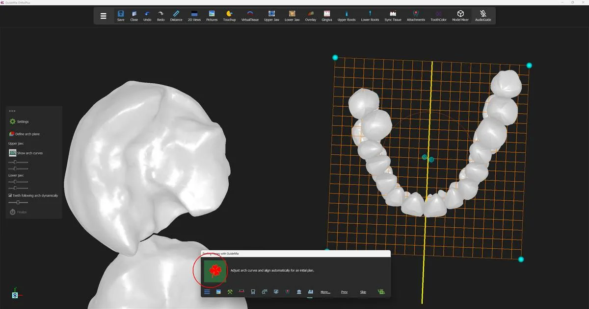
The Happy Button reads "Adjust occlusion plane for tooth alignment." The occlusal plane was already defined when the upper jaw was loaded, but it was defined against unsegmented scans. Now that GuideMia knows where each crown is, you get one more chance to place the plane against the teeth themselves, which is the surface every later judgement about extrusion, intrusion and the curve of Spee is measured from.

GuideMia brings the ortho planes into view and makes a single tooth current so you can see the plane in context. Turn the model and check that the plane sits where you would draw it. If it does, press the Happy Button; if not, "Define arch plane" on the panel shows it for adjustment.

The teeth numbered and the occlusal plane brought up for a last look before alignment. The teeth numbered and the occlusal plane brought up for a last look before alignment.
Arch curves and the treatment plan

The next press reads "Adjust arch curves and align automatically for an initial plan." Two things happen. The ortho planes go away and the arch curve appears, drawn through the arch on its own grid; and the Initial Treatment Plan dialog opens.

The arch curve is worth a moment before the dialog takes your attention. "Show arch curves" describes what you are looking at:

"This function will show and adjust the upper arch curve. There are two arch curves for each jaw. The default one is generated according to jaw width and length, and another one is simply a spline connecting the facial center points of the teeth. You can always adjust the control points on the arch curve to customize it."

Drag a control point and the teeth follow, because "Teeth following arch dynamically" is ticked by default:

"When this option is on, any changes to the arch curve will incur instant tooth movements so that you will know how the teeth will move according to the arch curves."

That live response is the fastest way to understand what a case will tolerate. Widen the posterior handles and watch how much crowding disappears.

The arch curve on its grid, with the width and curvedness controls on the panel. The arch curve on its grid, with the width and curvedness controls on the panel.
Saying what you want

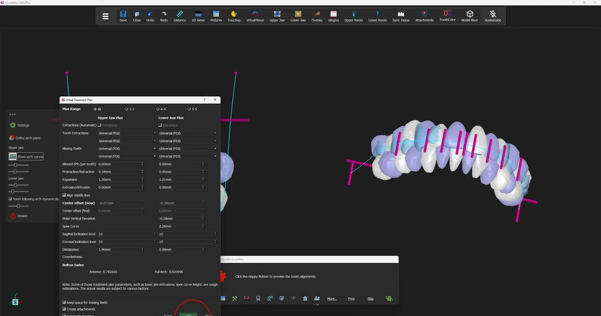
The Initial Treatment Plan dialog is where clinical intent is expressed — expansion, protraction and retraction, distalization, allowed IPR, midline, extractions, missing teeth. It has its own step in the support knowledge base and more controls than any other surface in the product. Three things about it change how you work in this step.

It is not modal. You can leave it open, turn the model, drag an arch handle, and come back to it. In the demo it stays open through the preview and the finalise steps, so the numbers can be watched as they change.

Values apply as you set them. A numeric field takes effect when you leave it, a checkbox when you click it. You do not press "OK" to make a value count. What "OK" does is start the next operation:

"This button will apply the parameters and generate initial plan. In case of automatic design, the tooth segmentation has not been performed, this will simply save the parameters for later use."

The crowdedness readout is usually blank, and that is the good outcome. The dialog only fills it in for values above 0 — and a case that fits has a crowdedness of zero or below. The real number, negative included, is written into the status bar at the bottom of the window: upper arch crowdedness is followed by the value. Read the status bar, not the dialog.

The dialog carries its own warning about how much weight to put on these figures, and it is worth repeating to anyone who asks:

"Note: Some of those treatment plan parameters, such as lower jaw extrusions, spee curve height, are rough estimations. The actual results are subject to various factors."

The Initial Treatment Plan dialog, with the real crowdedness value in the status bar at bottom left. The Initial Treatment Plan dialog, with the real crowdedness value in the status bar at bottom left.
The preview

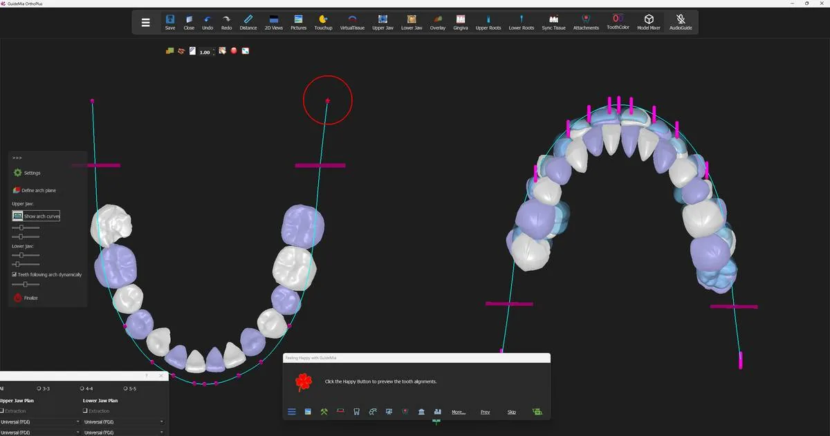
Press the Happy Button again — "Click the Happy Button to preview the tooth alignments." — and GuideMia arranges the teeth. It does this at 98% of the way to the ideal arch, using the smile-correction control on the panel, whose own description explains the scale:

"This value changes of this slider will update the preview of the initial tooth alignments. The slide value will indicate the percentage the teeth will likely be moved. 100% means the teeth will be moved to the ideal arch curves."

Nothing is committed. The preview is a proposal you can reject by changing a plan parameter or an arch handle and previewing again, and the demo does exactly that — the protraction and distalization figures in the dialog move between one preview and the next as the arch is adjusted.

The proposed positions previewed against the arch curve, with the starting positions still visible behind them. The proposed positions previewed against the arch curve, with the starting positions still visible behind them.
Finalising

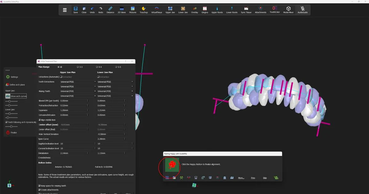
The fourth press reads "Click the Happy Button to finalize alignment." This is the one that commits, and it does more than accept the preview:

"Finalize the tooth setup. Once the initial preview looks fine, you can click this button to finalize the setup. This will involve steps to adjust collisions and IPRs, to move teeth according to Spee curves, etc."

If attachments were asked for in the treatment plan — "Create attachments" is ticked by default — they are placed before the movement data is worked out, so the plan accounts for them rather than having them added afterwards. That is why the arch you see at the end of this step already carries attachments.

GuideMia then fills in the movement data, hides the ortho planes in both 3D windows, and moves the panel from "Automatic Planning" on to "Planning Final Positions" — the manual tooth setup tools, which are step 8.

Finalising the alignment, with the treatment plan still open beside it. Finalising the alignment, with the treatment plan still open beside it.
Judging what came back

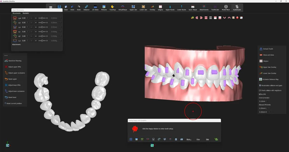
The Happy Button now offers "Click the Happy Button to enter tooth setup." Do not press it yet. This is the point in the workflow with the best ratio of looking to fixing.

Turn the model and look for four things.

Does the arch read as an arch? From the occlusal view the crowns should sit on a smooth curve with even contacts. A tooth that sits visibly off the line its neighbours describe, or that has been rotated much further than the case called for, is usually one whose mesial-distal direction was read wrongly during segmentation.

Does the bite make sense from the front and the side? GuideMia aligned each arch onto its own curve; whether the two arches meet sensibly afterwards depends on the articulation you supplied in the scans. Anteriors that finish edge-to-edge, or a midline that has walked, point back at the bite in the scan files rather than at the alignment.

Is any crown malformed? A crown that comes through the alignment torn, notched, or missing part of its surface did not become that way here — it was segmented that way, or the scan did not cover it. It will still be movable, but it will make a poor aligner, so deal with it before staging.

Are the attachments on the teeth you expect? They were placed against the final positions, so a strangely placed attachment is often the first visible sign that a tooth's orientation is wrong.

If everything looks right, the alignment is done and you can go on. If it does not, the fixes live upstream — in segmentation, in the crown boundaries, or in the scan itself — and it costs one step to go back now against several later.

The display maps are the other half of this inspection. Turning them on and off from the right-click menu is how you check contacts and how far individual teeth are being asked to travel; step 7 covers what each one colours and what the colours mean.

The finished alignment: both arches on their curves, attachments in place. The finished alignment: both arches on their curves, attachments in place.
Where you are now

The case has a proposed final position for every tooth, with attachments, and a first set of movement figures behind them. Nothing is staged yet — there are no steps and no aligners, only a starting arrangement and a target arrangement. Turning the target into something you would actually treat is the next two steps: adjusting individual teeth and making room for them in step 8, then breaking the movement into steps in step 9.

More on this page

The "Automatic Planning" section of the workflow panel carries more than the four Happy Button presses use:

ControlWhat it is for
"Settings"The movement profile — how much total and per-step movement GuideMia will plan
"Plan movements from step"Keeps existing steps up to a given step and replans only after it
"Define arch plane"Shows the arch (occlusal) plane so it can be adjusted
"Show arch curves"Shows and adjusts the arch curve for the jaw you are on
"Teeth following arch dynamically"Teeth move as you drag the curve; on by default
"Upper jaw:" / "Lower jaw:" width and curvednessShape the curve without dragging handles
"Smile Correction"The preview percentage; the Happy Button sets it to 98
"Finalize"Commits the setup, adjusting collisions, IPRs and the Spee curve

Below it sits "Arch Curve Control", a third way to move teeth that the demo does not use. It works from an arch control curve rather than the arch curve: "Show and adjust arch plane (Crown center level is suggested)" places the plane, "Update/show upper arch control curve" builds a curve from it, and "Adjust upper teeth by arch" snaps the teeth toward it —

"This function will snap the teeth toward the control curve. You can combine this tool and the arch curve adjustment to obtain the best results. After this operation, use the button below to adjust IPRs and gaps."

That last sentence is the pattern for the whole of step 8: move teeth, then settle the contacts.

Step 7 of 13

Reading the model — the display maps

The colour overlays for contacts, occlusion and movement that steps 6, 8 and 9 all point back to.

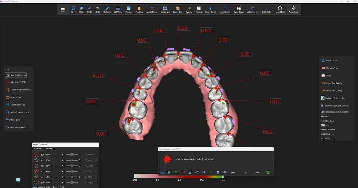
This step is not a step. It is the reference the rest of the guide sends you to: three colour maps that GuideMia can paint onto the models, what each one measures, and when in the workflow you would want it on.

They matter because most of what you need to judge about an aligner case is not visible on a white model. Whether two crowns are touching or 0.3 mm apart, whether a root is being pushed through the buccal plate, whether the bite has opened where you were not looking — none of that is legible from shading. The maps make it legible.

They also matter because they are modes, not readouts. A map stays on until you turn it off, and a model wearing a colour map does not look like the model you are used to. If a jaw suddenly renders in unfamiliar colours, the first thing to check is whether a map is on.

Where they live

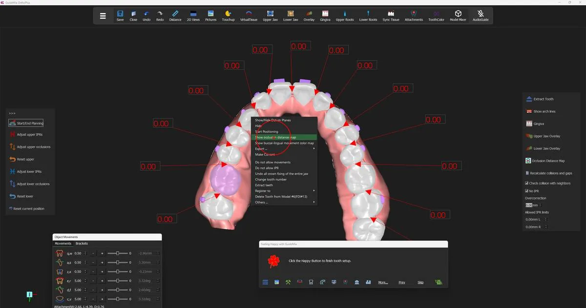
All three are on the right-click menu in the 3D windows. Right-click on the model — a tooth or a jaw, depending on the map — and the items sit near the top of the menu, above "Export ...".

The captions are toggles, so what you see tells you the current state: "Show occlusion distance map" when it is off, "Hide Occlusion Distance Map" when it is on. The same is true of the other two.

One consequence of them being on the right-click menu: opening that menu collapses the extra handles on the placement widget of whatever tooth you were moving. Re-select the tooth and they come back.

The right-click menu on a tooth, with the two map items above "Export ...". The right-click menu on a tooth, with the two map items above "Export ...".
Occlusal Distance Map

What it colours. Every point on the crowns of the current jaw, by how far away the opposing jaw is at that point. A colour scale appears at the bottom of the 3D window while the map is on, running from −2.0 to 0.0 in millimetres.

How to read it. Pale and neutral where the opposing surface is roughly 2 mm clear. As the clearance closes the surface reddens. The green end of the scale is contact — where the two arches actually meet. A red patch with a green centre is a contact point and the surface falling away around it.

What it tells you clinically. Where the bite is carrying load and where it is not. A posterior segment that stays pale while the anteriors are green is an open bite in the making. A tooth that is green over most of its occlusal table rather than at cusp tips is over-occluded against its opponent.

When to turn it on.

  • After the first alignment (step 6), to see what the proposed arrangement does to the bite.
  • Throughout movement planning (step 8) whenever you have moved a tooth vertically — intrusion and extrusion are the two movements whose occlusal consequence is hardest to see any other way.
  • Before staging (step 9), as a last check on the final positions.

What it needs. An optical jaw or tooth model. It is available from the moment the scans are loaded, which is why it is used as far back as crown boundary work.

The occlusal distance map on the upper arch, with its −2.0 to 0.0 mm scale. The occlusal distance map on the upper arch, with its −2.0 to 0.0 mm scale.
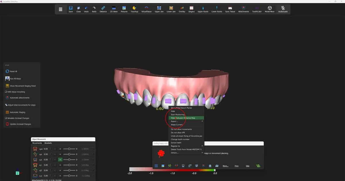
Bone density map

What it colours. The virtual roots, by the density of the bone they sit in.

How to read it. As a warning surface rather than a measurement. Where a root runs out of dense bone, that is where the movement you are planning has the least support.

What it tells you clinically. Whether a planned root movement — torque, bodily translation, uprighting — is asking a root to travel into bone that will carry it, or through a plate that will not.

When to turn it on. During movement planning, on any tooth whose plan involves significant root movement rather than crown tipping.

What it needs. A loaded CBCT and a virtual root on the tooth. The density it shows is measured density, so it exists only where there is radiographic data to measure. Turning the map on also turns virtual roots on, so the roots appearing at the same moment is expected, not a second command firing.

Buccal-lingual movement map

What it colours. The virtual root of a tooth, by how much buccal-lingual movement that tooth is being asked to make.

How to read it. As a magnitude map over the root, so you can see not just that a tooth moves buccally but where along its length the movement is greatest — which is the difference between tipping the crown out and moving the whole tooth out.

What it tells you clinically. Which teeth in an expansion are doing the work, and whether they are doing it bodily or by tipping. On a case being expanded, this is the map that shows you which roots are being asked for the most.

When to turn it on. After the first alignment, when the arch has been widened and you want to see where the expansion actually landed; and during movement planning, on any tooth you are moving buccally or lingually by hand.

What it needs. A virtual root on the tooth. No CBCT is required — a pontic-style root from an optical-scan case is enough.

Turning them off

Right-click the same model and choose the item again — the caption will now read "Hide Occlusion Distance Map", "Turn off bone density map" or "Turn off buccal-lingual movement color map".

Turning a map off is a per-jaw operation: "Hide the occlusion map of the current jaw." If you have had the map on in both arches, you will turn it off twice, once in each 3D window. The demo does exactly that at several points — one right-click in the assembly window and one in the working object window.

Turning the occlusal distance map off again from the same menu. Turning the occlusal distance map off again from the same menu.
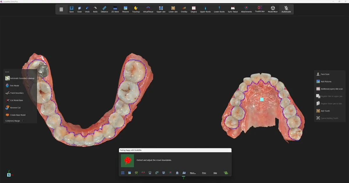
The model with no map on

Worth knowing what you are returning to. With every map off, the models render in whatever the current display mode gives you: the textured scan early in the workflow, plain crowns with tissue once the arches have been segmented and rebuilt.

The same arches with no map on — the textured scans during crown boundary work. The same arches with no map on — the textured scans during crown boundary work.
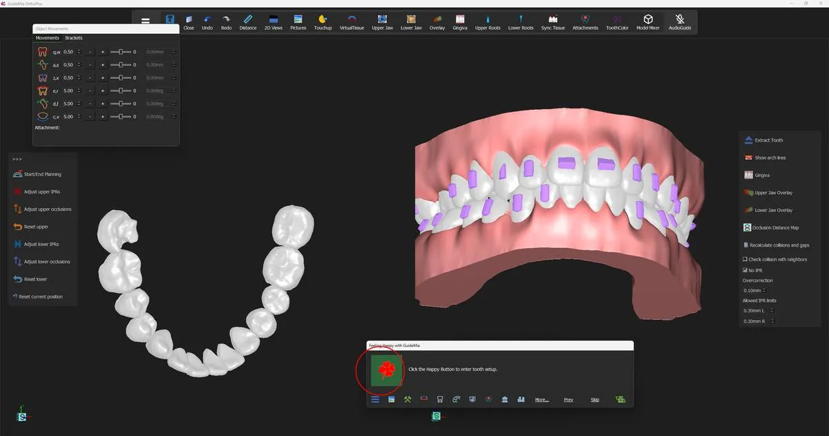
At a glance

MapColoursNeedsTurn it on to see
Occlusal Distance MapCrowns, by distance to the opposing jaw, −2.0 to 0.0 mmAn optical jaw or tooth modelWhere the bite touches and where it has opened
Bone density mapVirtual roots, by bone densityA loaded CBCT and a virtual rootWhether a root movement has bone to travel into
Buccal-lingual movement mapVirtual roots, by buccal-lingual movement amountA virtual rootHow much of an expansion is bodily and how much is tipping

More on this page

The maps are not the only display state reachable while you are inspecting a result. The same right-click menu carries "Show/Hide Datum Planes" and, under "Others ...", "Hide in 2D" / "Show in 2D" and "Change Color" — which recolours all teeth when used on a tooth, not just the one you clicked.

There is also a panel-side toggle. "Occlusion Distance Map" appears on the right-hand tool strip of the movement planning pages, and does the same job as the menu item for the jaw you are working on. Use whichever is nearer to hand; the state is the same one.

And if you have hidden something and cannot find it again: right-click on empty background in the assembly window and the "Show other objects" submenu lists everything currently hidden, by name.

Step 8 of 13

Movement planning and IPR

Adjust targets tooth by tooth, check interproximal reduction against the allowed limits, and settle the occlusion.

The automatic alignment gave you a target: a position for every tooth, arrived at from arch curves and treatment-plan parameters. It is a good target and it is not a finished one, because the software optimised an arch, not a patient. This step is where you take that target apart tooth by tooth and put it back together as something you would treat.

Two kinds of work happen here and they feed each other. Moving teeth is the obvious one — a canine that wants a degree less rotation, an incisor that should sit half a millimetre further lingual. Interproximal reduction is the other, and it is what makes the moving possible: teeth cannot occupy the same space, so every position you improve on one tooth has to be paid for in space taken from somewhere along the arch.

You will go round that loop several times. Move, settle the contacts, look at what the settling did, move again. The software is explicit that this is normal — its own description of the IPR tool says "Some times this may need to be done multiple times" — and a case that needs three passes is not a case that has gone wrong.

Nothing here is staged yet. Everything you do in this step changes the final positions. Steps come in step 9.

Entering tooth setup

Press the Happy Button at "Click the Happy Button to enter tooth setup." The panel opens on "Planning Final Positions" and presses "Start/End Planning" for you. That toggle is what puts the case into manual setup, and its own description is the definitive account of how a tooth is moved:

"When this button is pressed down, the system will show upper and lower teeth in different rendering options, and all the other models except upper tissue model will be hidden. You can click on any tooth and adjust the tooth positions."

You can press it again at any time to step out, and again to step back in. Everything in this step is done with it down.

The case in tooth setup: the working object window on the left, the assembly on the right, and the manual tools on the panel. The case in tooth setup: the working object window on the left, the assembly on the right, and the manual tools on the panel.
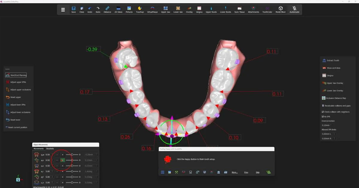
Three ways to move a tooth

GuideMia offers the same movement three ways, and which you reach for depends on whether you know the number you want.

The placement widget. Click a tooth and handles appear around it. Drag them to translate and rotate. The middle mouse button drags the tooth directly. This is the fastest way to explore — you can see immediately whether a tooth has anywhere to go.

The "Object Movements" dock. Six sliders, one per axis: mesial-distal, buccal-lingual, extrusion-intrusion, rotation about the tooth's vertical axis, torque about its mesial-distal axis, and tipping. Each has a step-size field and a pair of "+" and "-" buttons that nudge by that step. Beside them, six read-only fields report the resulting movement in millimetres and degrees — so the dock is both the control and the readout. When you drag a slider, GuideMia may reorient the object window so you can see the movement you are making.

This is the one to use when you want 0.5 mm buccal, not a bit buccal.

The keyboard. For left-handed working the first three columns of alphabet keys move and rotate; for right-handed working the arrow keys plus Page Up and Page Down. The dock labels each axis with its key pair — "q,w", "a,s", "d,f", "z,x", "c,v", "e,r" — so the mapping is on screen while you learn it.

Moving several teeth at once. Control or Shift with the left mouse button selects multiple teeth. The placement widget only appears on one of them, but it moves all of them.

Linked mode is a different thing and the two are easy to confuse. "Upper Linked Mode" and "Lower Linked Mode" make the neighbours of the tooth you move follow it by a gradually reducing amount:

"When a selected tooth is moved, the adjacent teeth will move in the same way but by gradually reduced amount. This is called linked mode. This is not same as to move multiple teeth together. If you are selecting and moving multiple teeth together, make sure you turn off the linked mode."

Linked mode is for smoothing a segment. Multi-select is for moving a block rigidly. Running both at once gives you neither.

Watching the contacts while you work

Tick "Check collision with neighbors" before you start moving anything.

"This option will turn on and off the visual feedbacks of collisions and gaps between adjacent teeth."

With it on, every interproximal contact along the arch carries a number, live, updating as you move. A positive value in red is a collision — the two crowns overlap by that many millimetres. A negative value in green is a gap. Zero is a clean contact.

This changes how manual adjustment feels. You are not moving a tooth and hoping; you are watching the two numbers either side of it as you go, and you can see the moment a rotation you like starts costing 0.3 mm of overlap on the distal.

"Recalculate collisions and gaps" forces the numbers to refresh if you have been working somewhere that did not trigger an update.

Moving a lower incisor by hand, with the interproximal collision and gap values live along the arch. Moving a lower incisor by hand, with the interproximal collision and gap values live along the arch.
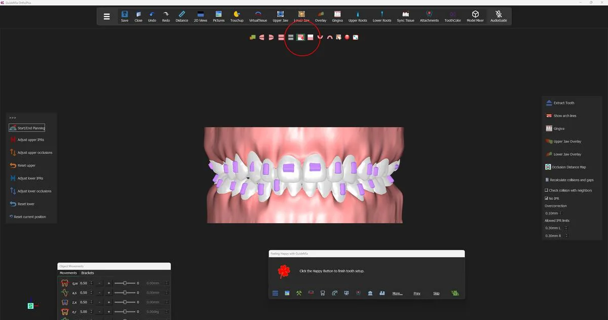
Seeing the setup properly

Manual setup rewards looking from more angles than you think you need. The view buttons on the toolbar give you "Front view", "Left view", "Right view", "Top view" and "Bottom view" as single clicks, plus a "Front view" variant described as "Front side view for the assembly window. Upper jaw only." — the upper arch alone, from the front, which is how you check anterior alignment without the lower teeth in the way.

There is also a "Resize Window" button:

"This button will maximize the current image window or restore the regular layout."

Two 3D windows side by side is the right layout for most of the work; one window filling the screen is the right layout for judging the anteriors.

The upper and lower anteriors from the front, mid-setup. The upper and lower anteriors from the front, mid-setup.
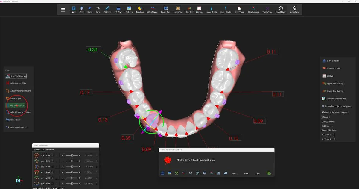
What IPR is for here

Interproximal reduction is how you create the space the arch does not have. GuideMia treats it as a planning quantity: you say how much you will allow, per tooth and per side, and it plans inside that.

The default is none. "No IPR" ships ticked. Until you clear it or set allowed limits, GuideMia will solve crowding by moving teeth along the arch and nothing else. That is a deliberate default and it is the right one — IPR is irreversible on a real patient, and software should not spend it on your behalf.

Three controls set the budget:

  • "No IPR" — the master switch. Tooltip: "Allow/disallow IPR".
  • "Allowed IPR limits" — two fields, suffixed "mm L" and "mm R", for the left and right side of the currently selected tooth. This is where you say this tooth may give up 0.3 mm mesially and nothing distally. (Both fields' tooltips read "left side"; the second one is the right side despite what it says.)
  • "Manual IPR Adjustment" — two read-only figures with the same "mm L" and "mm R" suffixes, reporting the current collision or IPR value on each side of the tooth. These are the numbers you are managing.

"Update teeth according to IPRs" applies the allowed limits to the teeth directly, if you would rather set the numbers and have the software honour them than move teeth and see what the numbers become.

There is a ceiling above all of this. The movement profile — reached from "Settings" on the panel, or Tools > Settings — carries a total IPR limit that ships at 0.50 mm with a minimum of 0.05 mm, and cannot be set above 2.00 mm. If a case will not resolve inside the IPR you are offering it, that form is where the answer lives, and raising it is a clinical decision, not a software one.

"Overcorrection" sits beside these and does something different: "Maximum allowed translation of the tooth center." It is a per-tooth allowance, not an IPR control, and it is easy to change by accident when you meant to change the IPR limit below it.

Letting GuideMia settle the arch

When the manual moves are made, hand the contacts back to the software. "Adjust lower IPRs" and "Adjust upper IPRs" each do the whole jaw, and their description is the most useful paragraph on the page:

"This function will move teeth along the arch curve from or toward the middle incisors so as to remove collisions. If the allowed IPRs are set, this function will honor the allowed values. If the option to Check collusion with neighbors is turned on, the image window will instantly show the current collisions or gaps. Some times this may need to be done multiple tmes to completely remove collisions between adjacent teeth. It is recommended to always use this function to finalize manual adjustment unless certain IPRs are desired and have been planned." [sic — "collusion", "tmes"]

Four things in that paragraph are worth pulling out.

It moves teeth along the arch, from or toward the midline. It does not grind crowns. It redistributes space by sliding teeth, and only spends IPR where you have said it may.

It honours your allowed values. Set the limits first, then run it. Run it first and it solves the arch with whatever budget is currently set — which, on a fresh case, is none.

It usually needs more than one pass. Removing a collision at one contact shifts the tooth that was causing it, which can open or close the contact on its other side. The demo runs the lower jaw twice.

It is the recommended way to finish manual work. Unless you have planned specific IPR values and want them exactly, end every round of hand-adjustment by running it.

The lower arch after the first IPR pass: remaining collisions in red, a gap in green at the left molar. The lower arch after the first IPR pass: remaining collisions in red, a gap in green at the left molar.
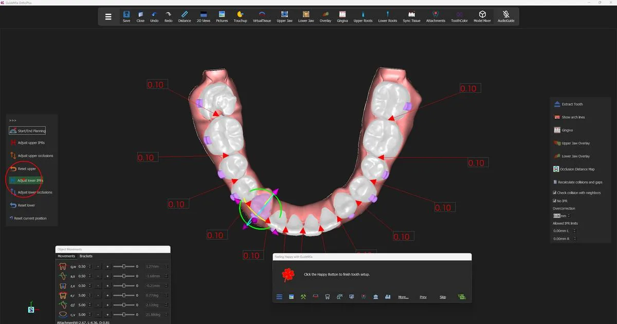
Run it, then read the arch. The figures that come back tell you what to do next: values in the low hundredths are contacts you can leave; a stubborn larger value at one contact is a tooth that needs moving by hand or an IPR allowance it has not been given.

The same arch after re-running the IPR adjustment. The same arch after re-running the IPR adjustment.
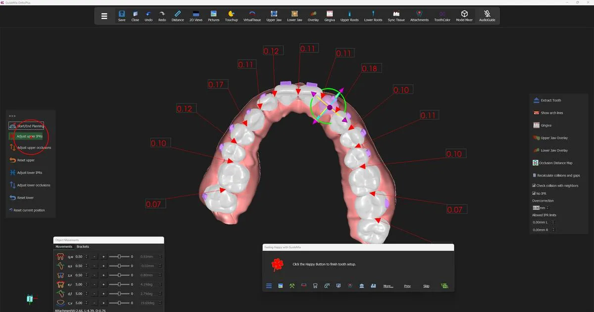
Then do the upper jaw the same way. The two arches are adjusted independently — each has its own button, its own linked mode and its own reset.

The upper arch after its own IPR pass. The upper arch after its own IPR pass.
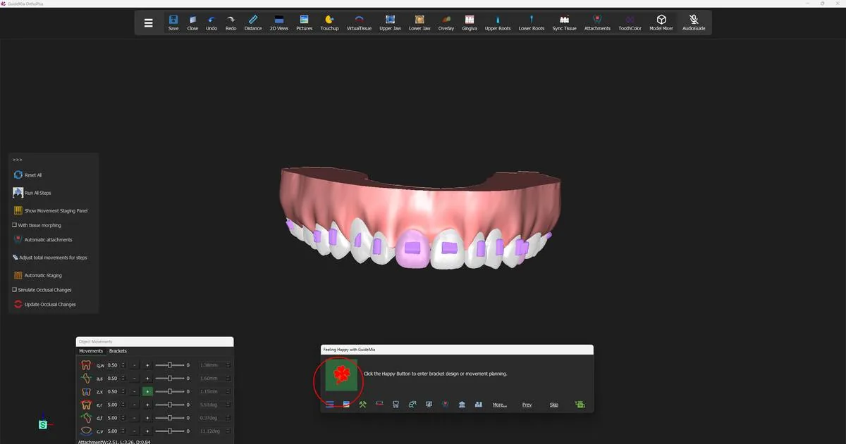
Backing out

Three resets, at three scales, all on the panel:

  • "Reset current position" — the tooth you have selected, back to where the automatic alignment put it.
  • "Reset upper" / "Reset lower" — every tooth in that jaw.

They reset positions, not the plan parameters. If a jaw has gone somewhere you do not like, resetting it and starting the manual pass again is cheap.

Knowing when to stop

There is no completion signal on this page — the Happy Button will let you leave whenever you press it. The judgement is yours, and it comes down to three questions.

Are the contacts clean? Every interproximal figure at or near zero, with no collision you have not deliberately accepted, and no gap you did not intend to leave.

Is every movement one you would actually ask for? Look at the numbers in the Object Movements dock, tooth by tooth, not just at the shape of the arch. A tooth that reads 12 degrees of torque has a plan behind it whether you meant it or not.

Does the IPR add up to something you will do? The allowances you set here become instructions on the treatment report. Total them mentally per contact and per arch, and be sure it is reduction you would perform.

When those three read right, press the Happy Button — it offers "Click the Happy Button to finish tooth setup." — and the case moves on to staging.

Where you are now

Every tooth has a final position you chose rather than inherited, the contacts between them are settled, and the interproximal reduction the plan depends on is written down against the teeth that will receive it. What does not exist yet is any notion of when — no steps, no order, no aligners. Step 9 turns the distance between where each tooth is and where you have put it into a numbered sequence.

More on this page

The "Planning Final Positions" section of the workflow panel, and the right-hand tool strip beside it:

ControlWhat it does
"Start/End Planning"Enters and leaves manual tooth setup
"Plan movements from step"Keeps existing steps up to a given step; replans only after it
"Upper Linked Mode" / "Lower Linked Mode"Neighbouring teeth follow the moved tooth by a reducing amount
"Adjust upper IPRs" / "Adjust lower IPRs"Slides teeth along the arch to remove collisions, inside the allowed IPR
"Adjust upper occlusions" / "Adjust lower occlusions"Moves that jaw's teeth vertically using the opposing jaw as the reference
"Reset upper" / "Reset lower" / "Reset current position"Undo at jaw and tooth scale
"Current Tooth ID"Which tooth the per-tooth controls apply to
"Overcorrection"Maximum allowed translation of the tooth centre
"No IPR"Master allow/disallow for interproximal reduction; ticked by default
"Allowed IPR limits" ("mm L" / "mm R")The budget for the current tooth, per side
"Manual IPR Adjustment" ("mm L" / "mm R")Read-only: current collision or IPR value per side
"Update teeth according to IPRs"Applies the allowed limits to the teeth
"Recalculate collisions and gaps"Refreshes the interproximal figures
"Check collision with neighbors"The live collision and gap display
"Occlusion Distance Map"The map from step 7, for the current jaw
"Extract Tooth"Marks a tooth for extraction from here
"Show arch lines", "Gingiva", "Upper Jaw Overlay", "Lower Jaw Overlay"Display toggles for judging the setup

Two tools that the demo does not use but that a harder case will want:

"Crown Morphing" rebuilds a crown that a large movement has made look wrong:

"For some situations, for example, a tooth has a big extrusion, this function will make the crown looks longer. When the tooth has large rotation angle, this function can reduce the soft tissue twist and repair the tooth model when the facial area has missing part."

The placement widget has a square handle for the same problem — fixing soft tissue twist when a tooth's rotation is large.

"All Teeth Fine Adjustment" does a pass over the whole arch:

"Perform fine adjustment for all the teeth. This tool is specifically for the situations that the tooth alignements are not idea but not too bad." [sic]

Read that scope literally. It is for tidying an arrangement that is nearly right, not for rescuing one that is not.

Step 9 of 13

Staging and simulation

Automatic staging into steps, the movement table, the per-step limits in the movement profile, and playing the simulation.

Up to now the case has had two states: where the teeth are, and where you have decided they should end up. An aligner case cannot be made from two states. It has to be a sequence — a numbered series of positions, each close enough to the last that a tray can move a tooth from one to the next.

Staging is where that sequence is created, and simulation is how you check it. Together they answer the question the whole plan has been deferring: how many aligners, and does anything crash into anything else on the way?

The Happy Button reaches this stage with the message "Click the Happy Button to enter bracket design or movement planning." and its icon turns blue. That colour change is the visual marker that the case has crossed from planning into design.

The Movement Planning page, with the staging and simulation tools on the panel. The Movement Planning page, with the staging and simulation tools on the panel.
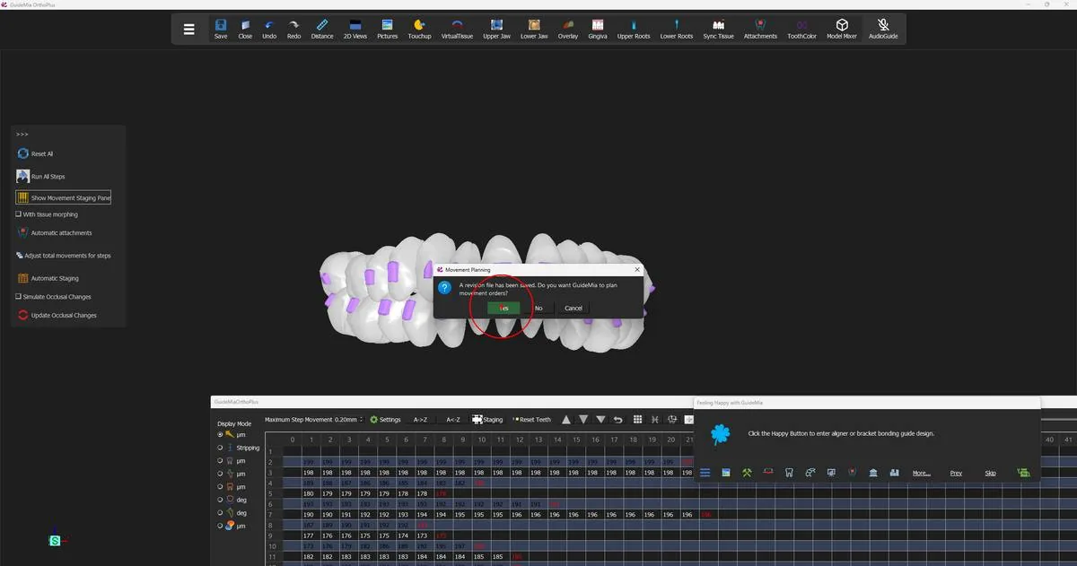
Planning the steps

"Reset All" is how the sequence is built or rebuilt:

"Reset the movement plans for all the teeth. This is to reset the steps but not change the final tooth positions. This function is not reversible. If you are working on a case that has gone through a part of the actual treatment, this can lead to wrong movement data for the current step."

Read both halves. It does not touch your final positions — everything from step 8 survives it. It does throw away every step that exists, and it cannot be undone. On a fresh plan that is exactly what you want. On a case where part of the treatment has already been delivered, it is the one button on this page to leave alone; the "Plan from step" control exists for that situation instead, and replans only the steps after a point you nominate.

GuideMia asks before it proceeds:

"A revision file has been saved. Do you want GuideMia to plan movement orders?"

Answer Yes and it distributes each tooth's total movement across steps. When it resets a tooth's plan it "simply regenerates equally distributed movements" — an even ramp from start to finish, which is the sensible default and not yet a considered order of operations.

GuideMia confirming before it plans the movement orders. GuideMia confirming before it plans the movement orders.
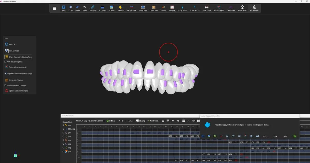
What decides the number of steps

Nothing on this page sets the step count directly. It falls out of arithmetic: the largest movement any tooth has to make, divided by the most that tooth is allowed to move in one step.

Those per-step maxima live in the movement profile, reached from "Settings", and you can change them. The one that usually governs is crown-centre translation, which ships at 0.20 mm per step — and that figure is shown on the staging toolbar as "Maximum Step Movement", so you can see the constraint while you read the table it produced. Per-step rotation, torque and inclination start at 2 degrees each; extrusion and intrusion at 0.10 mm.

Those are starting values, not fixed limits. Raising a maximum shortens the case and lowering it lengthens the case, and which figures are right is a clinical decision that belongs with your own protocol rather than with this guide.

So a tooth with 4 mm of translation to deliver needs at least twenty steps, and no amount of staging cleverness will make it fewer. If a case comes out longer than you expected, that form is the answer. "Upper Steps" and "Lower Steps" on the panel show the current maximum per jaw and can be edited, which asks GuideMia to plan within a limit you set rather than the one it derived.

Running the simulation

"Run All Steps" plays the plan:

"Simulate the movements of all the teeth and all steps. You can always rotate and zoom the 3D image windows while the simulation is running. You can also perform some other operations, such as turn on and off root display, but you should not expect to change workflow pages or actually change any model geometries."

That permission is worth using. The simulation is not a video you watch passively — turn the model while it plays, come round to the lingual, drop to the occlusal view. A collision that is invisible from the buccal is often obvious from above. "Run All Steps Repeatedly" loops it until you press the button again, which is the right mode for that kind of looking.

Two options change what you see. "Run Selected Teeth" simulates only the teeth you have picked, which is how you follow one problem tooth without the rest of the arch distracting you. "With tissue morphing" shows the soft tissue and deforms it with the teeth:

"If they don't follow the teeth, try the function Run All Steps again. If the problem persists, you can try to use the function Synchronize Tissue, which can be found on the system toolbar."

That toolbar button is "Sync Tissue".

The plan playing back, with the model free to be turned while it runs. The plan playing back, with the model free to be turned while it runs.
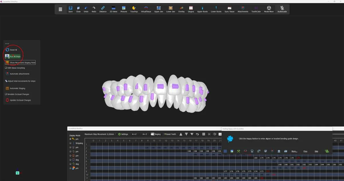
Viewing one end from the other

Two controls on the staging toolbar let you see where a plan starts and where it finishes at the same time, which is the honest way to judge how much movement is actually being asked for:

  • "A->Z" shows the final positions as the reference and sets the teeth back to the beginning.
  • "A<-Z" shows the initial positions as the reference and moves the teeth to the final position.

They are the same comparison from opposite ends. Use "A->Z" when you want to see the journey ahead of the teeth as they are now, and "A<-Z" when you want to see how far they have come. Either way you get one arrangement solid and the other as reference, in one view, without stepping through.

"Reset Teeth" returns the selected tooth to an evenly distributed plan if you have been experimenting.

Running the simulation, with the staging toolbar and the movement table below. Running the simulation, with the staging toolbar and the movement table below.
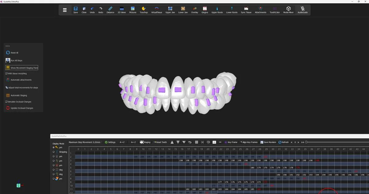
The movement table

"Show Movement Staging Panel" brings up the table at the bottom of the window — the surface where the plan stops being a picture and becomes numbers you can edit.

"The rows are corresponding to teeth and the columns to the steps. When there is no movement for a tooth in a step, the step will show no number. When a step is defined as a keyframe, the text in the cell will be shown in red."

So the shape of the table is the plan. A row that is blank until column 9 is a tooth that does not start moving until step 9. A row that stops early is a tooth that finishes early. Blank cells are stillness, not missing data.

What the numbers are depends on the "Display Mode" radio buttons down the left of the panel, and the default is translation in micrometres:

"We use a few sample points on a crown model, calculate the translation values of the individual points in one step, and use the maximum value to represent the tooth movement amount. The values in the table are in the unit of micro meters."

A cell reading 198 is 0.198 mm of translation in that step — which, against a 0.20 mm per-step maximum, is a tooth moving as fast as it is allowed to. Rows sitting just under the limit for their whole length are the ones setting the length of the case.

The other display modes re-read the same plan through different questions, and three of them are the ones you will actually switch to:

  • "Stripping" — when IPR can be performed on which teeth. "In general, IPRs are done at the beginning of a treatment, but sometimes the teeth may block each other, so the IPR has to be done at certain point in the treatment course when the teeth are no longer blocking each other." This is the mode that produces the clinical instruction sheet.
  • "Attachments" — which teeth need attachments and when they need reorienting. By default they are all added at the beginning.
  • Collision — where adjacent teeth interfere during the movement, step by step. Be ready to wait: "This will lead to the playback of all movements and collision calculation. It may take long time to complete the calculation."

Selecting a cell drives everything else. The tooth number and step number on the panel follow it, and the 3D views jump to that step — so clicking a red cell puts the model in front of you in exactly the position that cell describes.

The movement table: rows are teeth, columns are steps, red text marks key frames. The movement table: rows are teeth, columns are steps, red text marks key frames.
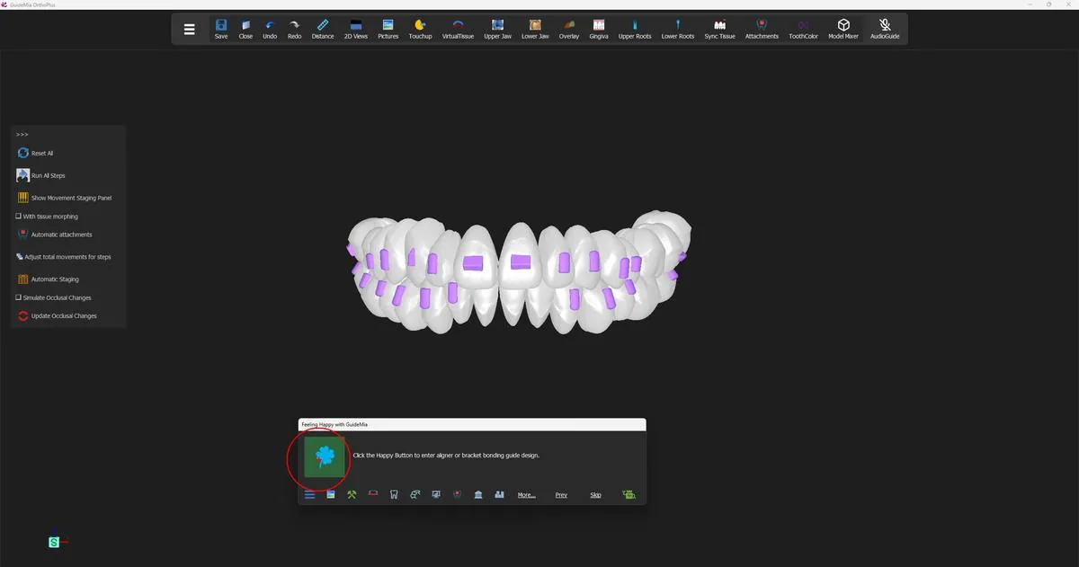
Key frames, and the quick route through this page

A key frame is a position a tooth must pass through:

"Key frame refers to a tooth position where the tooth will have to be during the movement process."

They are how you resolve a collision that even distribution created. If two teeth would clash halfway through, you pin one of them to a position that gets it out of the way, and the movement either side of that pin re-plans around it. Moving a tooth at a key frame changes how it travels, not where it ends up.

"Automatic Staging" does this across the whole case:

"This is an advanced feature to rerun all the tooth movements and adjust tooth positions in the middle of the simulation so that all the collisions will be eliminated. As a result, some steps may be added to the entire movement plan, and all the teeth will have their key frames set. ... In a quickest workflow, use the Reset All to plan all movements and use this button the finalize the plan."

That last sentence is the recommended path through this whole page: "Reset All" to build the sequence, "Automatic Staging" to make it collision-free. Expect the step count to rise — resolving a collision costs steps, and a plan that gained a few is a plan that found something.

The box beside it, suffixed "Steps/Stage", sets how often collision checking happens: "The smaller the number is, the more collision checking the system would do. Normally you would not need to change the settings, especially, to a bigger value."

Judging the plan

Before you leave this page, three checks.

Watch the whole simulation at least once, from more than one angle. You are looking for a tooth that travels through a neighbour, a tooth that lurches rather than moves smoothly, and anything that arrives at its final position early and then sits still for twenty steps for no reason.

Read the table for shape, not just values. Rows that all start at step 0 and all end together mean nothing has been sequenced — fine on a simple case, suspicious on a crowded one where some teeth clearly need space made before they can move.

Check the stripping mode against what you planned in step 8. The IPR you allowed becomes an instruction with a step number attached. If it is scheduled for step 14 rather than the beginning, that is the software telling you the teeth are blocking each other until then — worth knowing before someone tries to perform it at the first appointment.

"Save Revision" stores the staging plan as a revision, so a plan you are happy with can be kept while you try a different one.

Where you are now

The case is a sequence. Every tooth has a position for every step, the movements sit inside the per-step limits, key frames hold the plan clear of collisions, and the IPR is scheduled against the steps where it can actually be done. The Happy Button now reads "Click the Happy Button to enter aligner or bracket bonding guide design." — the case has everything it needs to be turned into arch models and aligners, which is the next step.

More on this page

The Movement Planning panel and the staging toolbar carry more than the demo uses:

ControlWhat it does
"Reset All"Rebuilds every tooth's steps; not reversible
"Plan from step"Replans only the steps after a nominated step
"Upper Steps" / "Lower Steps"The maximum step count per jaw; editable
"Run All Steps"Plays the whole simulation
"Run All Steps Repeatedly"Loops it until pressed again
"Run Selected Teeth"Simulates only the picked teeth
"With tissue morphing"Shows and deforms the soft tissue during playback
"Adjust total movements for steps"Spreads the load so fewer teeth move at once
"Automatic Staging"Sets key frames across the case to eliminate collisions
"Steps/Stage"How often collision checking happens
"Show Movement Staging Panel"Shows and hides the movement table
"Maximum Step Movement"The per-step translation limit, from the movement profile; editable in Settings
"Settings"The movement profile itself
"A->Z" / "A<-Z"One end of the treatment shown as reference while the teeth sit at the other
"Staging"Opens the stage planning tool
"Reset Teeth"Evenly redistributes the selected tooth's movement
"Key Frame"Marks the selected steps as key frames
"Align Key Frames"Gives several teeth a shared key frame, defining a stage
"Insert Step" / "Delete Step"Adds or removes a step at the selection
"Adjust Movement Amount", "Eliminate Collisions", "Move tooth at step"Fine control on the selected cells
"Save Revision"Saves the staging plan as a revision
"<", ">", ">>" and the step sliderMove the model through the steps by hand

Two more things the table itself can do. Right-clicking a cell opens the fine-control functions for that tooth and step. And cells can be dragged:

"For example, if a tooth has movements in step 2 to 10, you drag the cells from 7 to 10 to cell 15, it means the tooth will not move between step 7 and 15."

That is the quickest way to hold a tooth still while its neighbours get out of the way, and it is done entirely by selecting cells and dragging them.

For finer work than the table allows, the "Stage Planning" dock — opened by "Staging" — offers a before/after pair for each movement type ("Translation", "Rotation", "Intrusion/Extrusion", "Buccalingual Movement" [sic], "Mesialdistal Movement", "Arch Expansion", "Protrusion/Retraction", "Torque"), letting you push a whole class of movement before or after a chosen step. That is how you say expand first, then align, rather than doing everything at once.

Attachment scheduling lives on the same toolbar: "Start Attachment", "End Attachment", "End Attachment Intermittent Mode" and "Reset Attachment Staging" become available when the tooth selected in the table has an attachment, and set the steps over which it is active.

Step 10 of 13

Attachments

Automatic attachment placement per movement, the attachment library, and editing them tooth by tooth.

An aligner is a shell that grips the crowns. On its own a shell can tip a tooth and it can push it along the arch, but there are movements it cannot deliver because there is nothing on the smooth surface of the crown for it to hold. An attachment is the answer: a small piece of geometry bonded to the tooth, and a matching socket in every aligner that covers it, so the plastic has a purchase point and can apply the force in the direction the plan asked for.

That makes this the first stage of the guide where the work is about the appliance rather than the plan. Nothing you do here changes where a tooth ends up; the target positions and the staging are settled. What changes is whether the aligners you are about to generate can actually deliver them.

Attachments are also the last thing that can move before the models are built. Everything from here on — case tags, arch models, aligners — is generation, and generation reads the attachment set as it finds it. This is the page to be thorough on.

Getting to the page

The Happy Button reads "Click the Happy Button to enter aligner or bracket bonding guide design." Press it. Because there are no brackets on these teeth, GuideMia takes the aligner branch: the Aligner Design page opens and the button moves to the "Attachments" step, re-wording itself to "Automatically add attachments or force ridges."

You may find attachments already on the crowns when you arrive, as in the recorded case — GuideMia runs the automatic attachment tool as it leaves movement planning, so the first thing you see is a proposal rather than a bare arch. Pressing the Happy Button at this step runs that same tool again.

This case is run fully automatically: GuideMia decides the type, the shape and the size of every attachment, and the demo accepts what it proposes. That is one way to work and not the only one. You have full control over all three — every attachment on the arch can be changed to a different type, reshaped, resized, repositioned or removed, and you can place your own where the automatic pass put none. The rest of this step is that control: the automatic result first, then each of the tools that overrides it.

The teeth carrying their first set of attachments, with the Happy Button about to open aligner design. The teeth carrying their first set of attachments, with the Happy Button about to open aligner design.
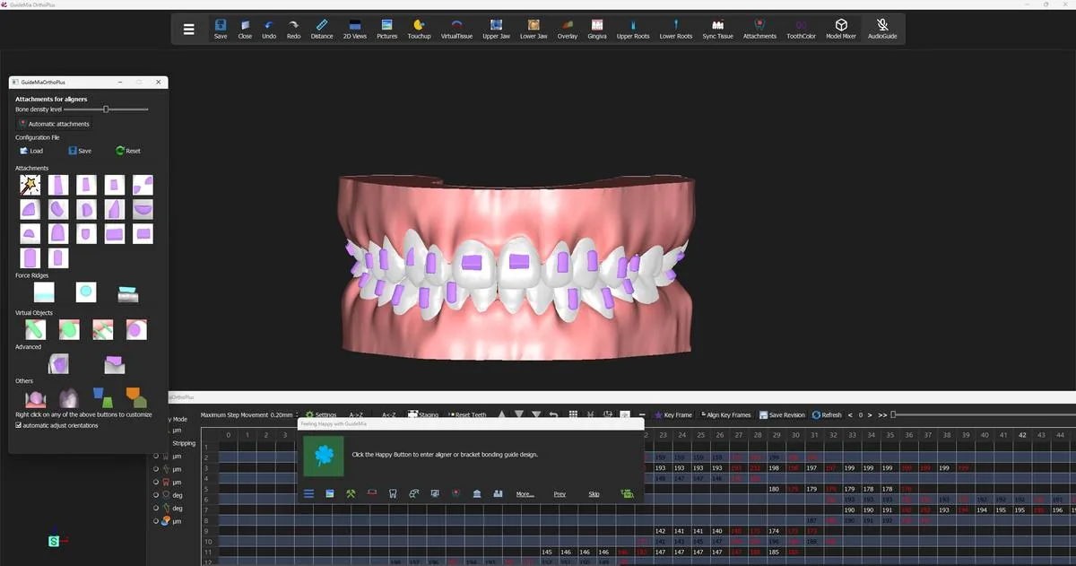
The workflow panel is hidden at this point in the demo, and this one step behaves differently from every other because of it: instead of building a sidebar, GuideMia floats the whole "Attachments and More" section as its own window, headed "Attachments for aligners". Every attachment tool in the product is on it.

The attachment tools floated as their own window beside the model. The attachment tools floated as their own window beside the model.
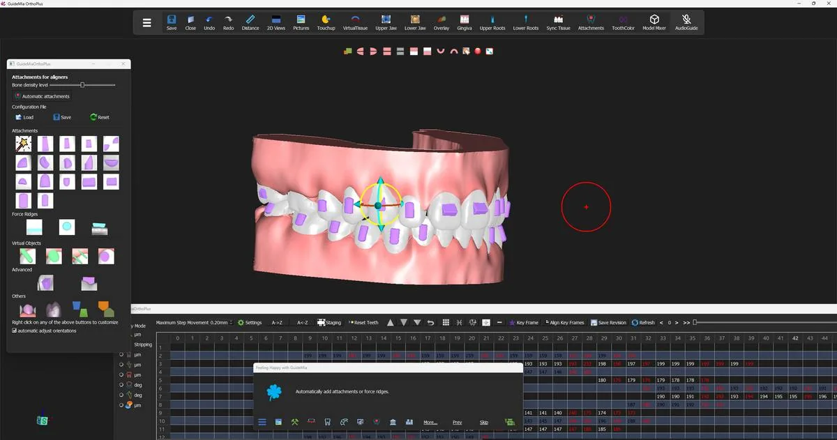
Clearing the view first

You have been looking at coloured analysis overlays for two steps — the buccal-lingual movement map, the bone density map on the roots, the occlusal distance map on the crowns. They are useful for judging a plan and they are in the way for judging geometry, because an attachment reads as a shape and a shape is hard to see through a colour scale.

Turn them off from the right-click menu in the 3D windows: "Turn off buccal-libgual movement map" [sic], "Turn off bone density map" and "Turn off Occlusal Distance Map". What is left is the crown surface and the attachments standing off it, which is what you are here to look at.

The automatic pass, and the one setting that steers it

"Automatic attachments" is the tool the Happy Button presses. GuideMia's own description of it:

"This is the automatic attachment tool. The system will automatically determine which teeth need attachments or force ridges, also known as power ridges, and what kind of attachments are needed, as well as how big they should be. The system has a full set of criterial to make the initial decisions, but you can always add, delete or modify the attachments or force ridges. ." [sic]

The last sentence is the working instruction for this whole step. The automatic pass is a starting point that is right most of the time, not a result to be accepted unread.

One control biases it, and it is worth setting before you press rather than after. "Bone density level" is a slider:

"This slider sets a rough bone density level. When the value is higher, the system tends to add more attachments or bigger ones when the automatic tool is used."

It is a judgement about the patient rather than about the software, and the setting is yours to make against your own protocol. Move the slider, then run "Automatic attachments" again to see what it changed.

"automatic adjust orientations" sits at the bottom of the window and is ticked by default. Leave it ticked unless you have a reason not to.

If your practice has settled on a house standard, the "Configuration File" buttons — "Load", "Save" and "Reset" — carry the attachment configuration between cases, so the automatic pass starts from your preferences rather than the factory ones.

Reviewing what it proposed

Rotate the arch and look at every attachment, from the buccal and from the lingual. Double-click one and GuideMia puts a bounding box and a manipulator around it; drag to move it, use the box handles to resize, and press Escape to finish the adjustment. The pop-up menu in the image windows deletes one you do not want.

An attachment selected for adjustment, with its manipulator on the crown. An attachment selected for adjustment, with its manipulator on the crown.
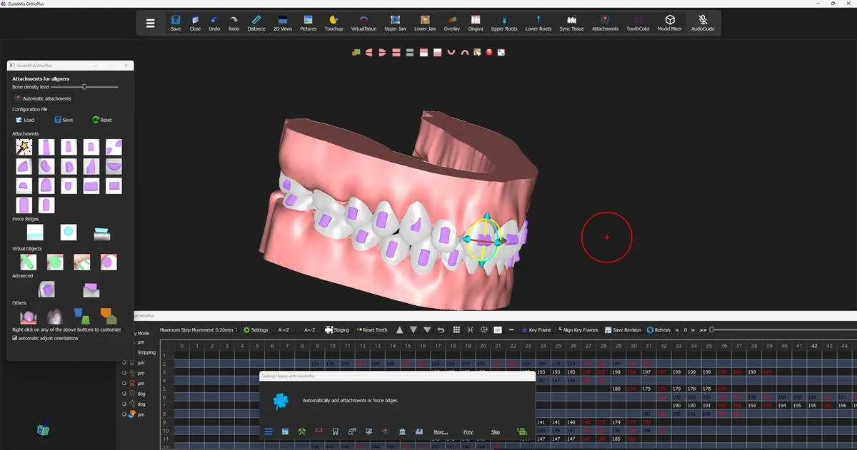
Turn the model right over and check the same attachments from below and behind. An attachment that looks well placed from the front is often the one sitting too close to the gingival margin, or running off the mesial edge of a crown that is still rotated at this step of the plan.

The same set checked from the side, with the model turned to bring the posterior teeth into view. The same set checked from the side, with the model turned to bring the posterior teeth into view.
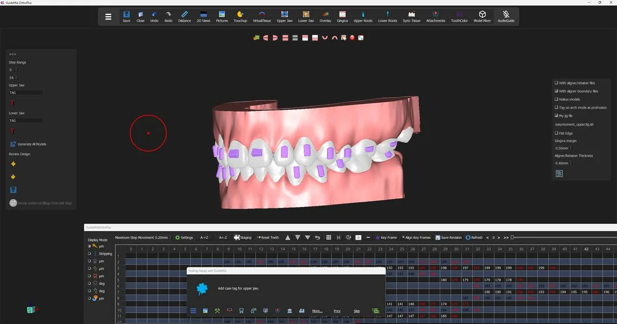
Two hard limits govern what you can do:

  • GuideMia allows one or two attachments per tooth. Not three.
  • With the type set to "Automatic", the system may decide no attachment is needed and add nothing. If you want an attachment on a particular tooth regardless, choose its type first and then place it.

Adding one by hand

The order matters. Set the Attachment type dropdown first, then switch on "Add Attachment", then click the tooth. An attachment of the chosen type appears with a bounding box; move and resize it, and click "Add Attachment" again to finalise. Double-clicking a finished attachment reopens it for relocation or resizing at any time.

"Smooth" exists for one reason, in the product's words: "Certain attachment models have sharp corners. This will fix it." Run it on any attachment whose edges look as though they would be uncomfortable against the mucosa or hard to release from the shell.

The shapes GuideMia offers

The attachment-type dropdown, in order:

Automatic | Regular Large | Regular Medium | Regular Small | Root Control Pair | Root Control Single | Rotation 1 | Rotation 2 | Rotation Single | Anchorage L | Anchorage S | Intrusion Torque L | Intrusion Torque S | Extrusion Anterior L | Extrusion Anterior S | Extrusion/Intrusion L | Extrusion/Intrusion S | Rectangular | Cylindrical | Triangle | Half cylinder | S Shape | Rounded Rectangle | Wedge | Dual bar | User defined

They fall into two families. The first group is named for the job — root control, rotation, anchorage, intrusion torque, extrusion — and is what you reach for when you know which movement on the staging table is the one you are worried about. The second group is named for the shape — rectangular, cylindrical, triangle, wedge, S shape, dual bar — and is what you reach for when you have a preference of your own and want to place it directly. Which shape suits which movement is a clinical decision and belongs with your protocol, not with this guide.

"User defined" takes an STL file of your own:

"When you select the user-defined, you can choose an STL file from your system and add it as attachment. If you use user-define, it is recommended to place the origin at about one third of the thickness from the bottom of the attachment file." [sic]

The buttons on the floating window are grouped under the labels "Attachments", "Force Ridges", "Virtual Objects", "Advanced" and "Others", and the window carries one line of instruction that is easy to miss and worth acting on: "Right click on any of the above buttons to customize".

Force ridges, and why they are not attachments

A force ridge — a power ridge — sits under its own label with a shape dropdown offering "Rectangular", "Spherical" and "Half cylinder", and "Add ForceRidge" placed exactly the way an attachment is placed. The difference is in what generation does with it:

"A force ridge is not added to the final arch models, instead it is subtracted from the arch models. Therefore what matters is the shape inside the tooth area, not the outside part."

Read that once more before you place one. Sizing a force ridge by how it looks standing proud of the crown is sizing the wrong half of it. The part that does the work is the part buried in the tooth, because that is the volume that will be cut away, leaving a bump on the inside of the aligner that presses on the crown. A "Smooth" button for force ridges sits beside the add button.

Cutouts and button platforms

Two more things get placed here, and neither of them changes the tooth.

Cutouts — "For a hook", "for a button", "For a tab" and "User Defined" — are placed with "Add Cutout", and GuideMia is explicit about their scope: "The cutouts will not impact the arch models. Instead, they will participate the generation of aligner trimming paths." They are windows in the finished aligner, not features of the model.

"Add Button Platform" is the other half of the same story:

"In case the clinicians want to use rubber bands to pull the teeth in the treatment, they may need to bond a button to the tooth. This function will create a cylindrical area so that the aligners can later on be made with this area available to bond th button." [sic]

If elastics are in the treatment plan, the platform and the cutout are placed together — one to give the button somewhere flat to sit, one to let the aligner clear it.

Where staging comes back in

Three things tie this page back to the movement plan you have just finished.

The automatic tool reads the plan. It decides which teeth need help and how much from the movements that are on the staging table, so an attachment set generated before you were happy with the staging is not the set you want; if you went back and re-staged, run "Automatic attachments" again and re-inspect.

Attachments ride the tooth. Whatever an attachment is bonded to takes it along through every step, so an attachment placed on a tooth that rotates heavily later in the plan will present a different face to the aligner at step 30 than it does at step 1. The steps in between are where to check that.

And changing an attachment has a cost in aligners. GuideMia warns about this on the design options you will meet in the next step, and the warning applies to any change made here: "any attachment changes like this may lead to additional aligners to be made as attachments template." An attachment that appears mid-course needs an aligner to bond it through.

Moving on

When the set is right, press the Happy Button. GuideMia moves to "Case Tag", the message becomes "Add case tag for upper jaw.", and the design sidebar appears in place of the attachment tools — step range, the two jaw tag fields, the generate buttons and the review transport.

The Attachments step finished; the design sidebar and the option strip appear, ready for the case tag. The Attachments step finished; the design sidebar and the option strip appear, ready for the case tag.
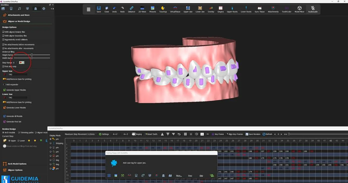
Where you are now

Every tooth that needs one carries an attachment, force ridges are placed and sized from the inside, and any cutouts and button platforms the treatment calls for are in position. The case is now fully specified: positions, staging and appliance features. The next two steps turn that specification into files.

More on this page

The demo runs the automatic tool and adjusts by hand. "Attachments and More" carries a good deal more:

ControlWhat it is for
"Bone density level"Biases the automatic tool towards more and larger attachments
"Automatic attachments"Places the whole set from the treatment plan
"Configuration File" — "Load", "Save", "Reset"Carries your attachment configuration between cases
Attachment typeThe type placed by the next manual add; set it before you click
"Add Attachment"Place one by hand; click again to finalise
"Smooth"Rounds off an attachment with sharp corners
"Add Button Platform"A flat cylindrical area for bonding an elastic button
Force-ridge shape"Rectangular", "Spherical", "Half cylinder"
"Add ForceRidge"Place a force ridge; it is subtracted from the model, not added
Cutout type"For a hook", "for a button", "For a tab", "User Defined"
"Add Cutout"A window in the aligner; the arch model is unaffected
"Anterior Bite Ramp"A ramp on an anterior tooth to open the bite so lower attachments clear
"Posterior Bite Ramp"The same idea on a molar occlusal surface
"Spacers (Virtual Teeth)"A virtual tooth placed between two teeth as an attachment
"Emerging cap/Replacing Tooth"A virtual tooth that occupies and inherits the movement of a real one
"Veneer"Adds veneers to teeth
"Twin blocks""This is an experimental function in this release."
"GuideMia wings for mandibular advancement""This is an experimental function in this release."
"automatic adjust orientations"Lets the automatic pass set attachment orientation; ticked by default
"Generate combined model for review"One PLY of crowns, attachments and soft tissue, for a quick third-party look

Two of these have a prerequisite that reaches back to step 4. A spacer is attached to a tooth and rotates with it, so "if a tooth rotates too much it is not recommended to attach the virtual tooth to it" — and GuideMia adds that this "needs to be take into account before the tooth segment" [sic]. If a case is going to need a virtual tooth in a heavily rotated site, the place to create it is the first page of the workflow, when the scans have only just been loaded.

Step 11 of 13

Case tags and generating the arch models

Put the case tag on the base, then generate the series of arch models — one per step — a lab prints and thermoforms over.

An arch model is a solid model of one jaw at one step of the plan. The lab prints it, thermoforms a sheet of aligner plastic over it, trims the plastic to the gingival margin and throws the model away. One model per jaw per step, which is why a fifty-step case is a hundred models and why the two decisions in this step — how many steps to build, and what to write on them — matter more than they look.

That second decision is the case tag. Once a hundred near-identical models are out of the printer and on a bench, the only thing distinguishing model 31 from model 32 is the text embossed on it. GuideMia puts the case's name and the aligner number on every model it builds, and it asks you where to put them before it builds anything.

This step covers the thermoforming path — arch models. Step 12 covers the other one, where GuideMia builds the aligner itself.

Opening the full panel

The design sidebar that appeared at the end of the last step carries the controls the Happy Button needs and not many more. Press ">>>" — "Turn on the full workflow panel and access more functions." — and the Workflow dock replaces both floating sidebars, with the Aligner Design page showing its four sections: "Attachments and More", "Aligner or Model Design", "Arch Model Options" and "Aligner Options".

Everything for the rest of this step is on "Aligner or Model Design".

The full workflow panel, with the design options, step range and generate buttons on one page. The full workflow panel, with the design options, step range and generate buttons on one page.
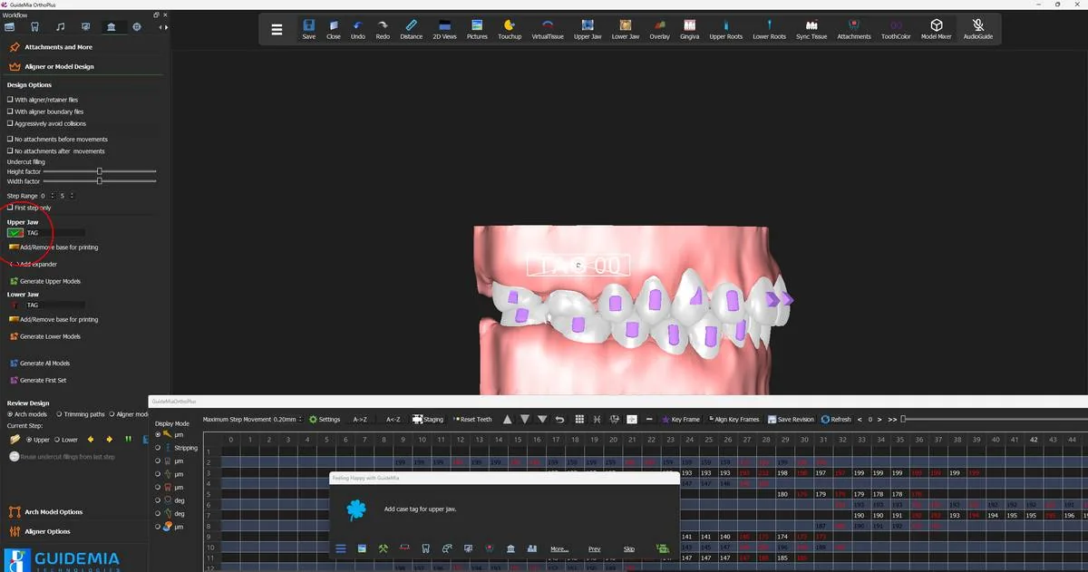
Checking the design options

Look at "Design Options" before you look at anything else, because the first checkbox decides what kind of file the generate buttons produce.

"With aligner/retainer files" is clear for an arch-model run. Ticked, it switches GuideMia to building aligners directly, which is step 12. Its own description says so:

"This aligner and retainer option tells the system to create aligner or retainer models for direct printing, instead of arch models for thermoforming."

The generate buttons are the same buttons either way, so this checkbox is worth a deliberate glance every time rather than a habit.

"With aligner boundary files" produces the trimming paths for automatic trimming: "In case you need to generate arch models with jigs for automatic aligner trimming, this option will generate trimming paths files. Each trimming path will include a coordinate file, and an STL file for review purpose." If your lab trims by hand you do not need it; if it trims on a machine you do, and the fixture settings under "Arch Model Options" become relevant.

Three more, all off in the recorded case:

  • "Aggressively avoid collisions" re-checks and adjusts for collisions that the staging should already have removed. GuideMia's own view of it: "It will slow down the process though, and normally is not very necessary."
  • "No attachments before movements" and "No attachments after movements" [sic — two spaces] leave an attachment off a model where the tooth has not started moving yet, or has already finished. They save model geometry, and both carry the same caution: "any attachment changes like this may lead to additional aligners to be made as attachments template."
  • "Undercut filling" has a "Height factor" and a "Width factor" slider governing the material GuideMia adds between the teeth.

Setting the step range

"Step Range" takes a start step and an end step, described as "The start step number to generate aligners or arch models" and "The final step number to generate aligners or arch models". It defaults to the whole plan — the recorded case had 54 steps and the boxes read 0 and 54.

Two reasons to narrow it. The obvious one is a re-run: a case where the first twenty aligners are already with the patient needs models 21 onwards, not 0 onwards. The less obvious one is verification, and it has its own control. "First step only" generates one model and nothing else:

"This option tells the system to only generate the first step. This is typica lly for verification purposes, and will not incur any cost even if you are using the software with a pay-per-lick license." [sic]

Print that one model, thermoform it, and you have proven the whole chain — the plan, the attachments, the fit, your printer, your sheet, your trimmer — before committing the other hundred. On a metered licence it costs nothing to do so.

The operator in the recording narrowed the end step to 5, which is the same idea applied to a demonstration: a short range that exercises every part of the process without waiting for a full arch.

The case tag

The tag is two operations, and the order matters: type the text, then place it.

Type the text first. The tag field starts out reading "TAG". Replace it with the case's identifier, under one restriction:

"Input the case tag here. Only alphabet letters and numbers. Do not include step numbers."

No step numbers, because GuideMia adds them. The recorded case was tagged demo, and the models came out reading DEMO L5 — the tag, the jaw, and the aligner number the model belongs to. That is the point of the field: you name the case once and every one of the hundred models labels itself.

Then place it. "Add/Update Case Tag" puts the text on the model at a default position, inside a bounding frame:

"This function will add the case tag to a default position, then you can manipulate it. The tag is added in different way for arch models or aligner models. The actual texts on the final arch models will have corresponding aligner steps on them. Click this button to finish when the tag placement is done."

Drag it, rotate it and resize it with the frame, then click "Add/Update Case Tag" again to finish. GuideMia's guidance on where to put it, given at this step:

"Generally, the tag should be far from the tooth area for arch models, and next to a molar at the distal side."

Far from the teeth, because the sheet has to draw down cleanly over the arch and a raised tag under the plastic is a defect waiting to happen. Distal to a molar, because that is the part of the model the aligner never covers and the part a technician can still read with the model in one hand.

The upper case tag placed on the model, inside its manipulation frame. The upper case tag placed on the model, inside its manipulation frame.
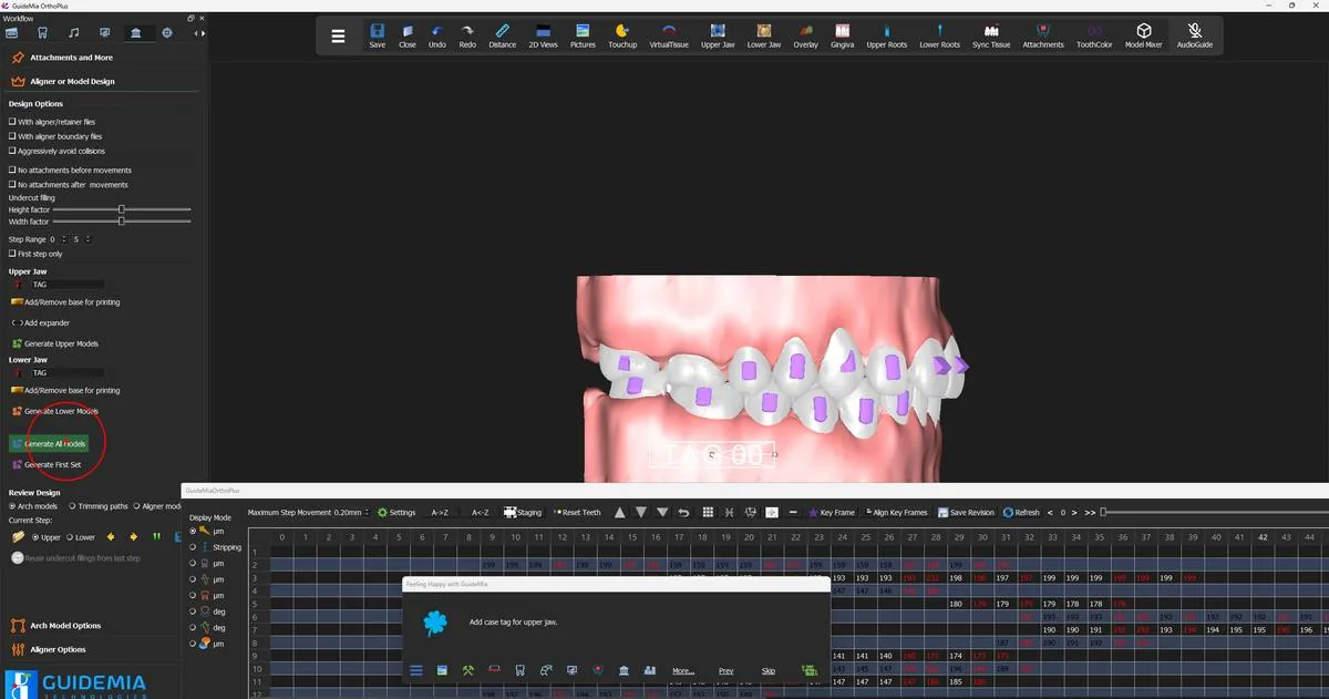
Then do the lower jaw. It has its own tag field and its own "Add/Update Case Tag" button, and it is a separate placement — the frame starts at the lower jaw's default position, not where you put the upper one.

Generating

Three buttons produce output, all carrying the same description: "Generate Upper Models", "Generate Lower Models" and "Generate All Models". The demo uses the last of the three.

"Generate the arch models or aligner models. All the models within the given step range will be generated for the upper jaw. The function will ask for a file name. Typically you want to create a new folder to hold the files. When you give the file name, do not use aligner numbers."

Both halves of that instruction earn their place. A new folder, because a full case is hundreds of files and they are much easier to hand to a lab as a directory than to pick out of a downloads folder. No aligner numbers in the name, because GuideMia appends them — files arrive as <name>_Upper_<n>.stl and <name>_Lower_<n>.stl, and a name that already contains a number produces something no-one can sort.

Alongside the models GuideMia writes an XML order file listing every step against its model file and the case serial number, and — on a run with a fixture — the trim-line file for each step. That manifest is what a lab's production system reads, so it belongs in the folder you send.

Generating every model in the step range for both jaws. Generating every model in the step range for both jaws.
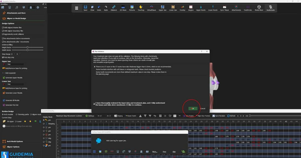
Plan Validation

Generation does not start immediately. GuideMia runs the plan through its validation criteria first and shows you what it found:

"Your treatment plan does not pass all the validation. The following items with checkmarks need your attention. If you wish to continue, click on the Ok button. Otherwise, cancel the operation. However you must be aware ignoring those criteria can result in invalid plan and unusable surgical guides."

Only the items actually marked apply to your case. On this case one is marked — "There is no CT scan or the CT scans have slice thickness bigger than 0.5mm, which is not recommended." — and it is expected, because this is an optical-scan case with no CBCT and has been since step 1. The other two lines in the list, on bracket interference and on step movements exceeding the defined maximum, are unmarked.

"OK" stays disabled until you tick the acknowledgement:

"I have thoroughly reviewed the input data and treatment plan, and I fully understand the issues and risks afore-mentioned. I'd like to continue."

That is deliberate. Read the marked items, decide whether each one is a known property of the case or a genuine problem, and only then tick and continue. An unmarked list is the software telling you the plan is clean; a marked one is the last chance to go back to the planning page.

Plan Validation, with the acknowledgement that enables OK. Plan Validation, with the acknowledgement that enables OK.
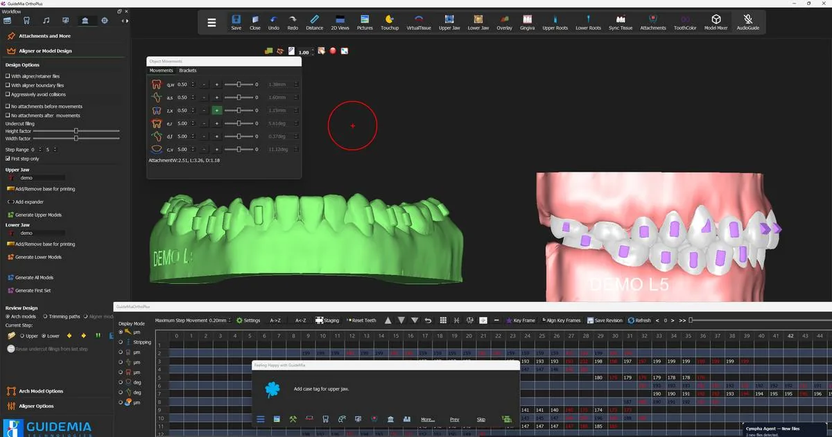
Once you confirm, GuideMia builds the models. The 3D window shows the work as it goes, jaw by jaw and step by step — a live preview of progress rather than an exact picture of the output files.

If generation completes without producing anything, the licence is the first place to look: output is metered, and an inactive licence or an empty credit balance stops files being written. See the licensing guidance rather than re-running the generation.

Reviewing what came out

"Review Design" at the bottom of the section is where you inspect the files without leaving GuideMia, and it is not merely a viewer.

"Arch models" is selected by default, and "Upper" and "Lower" choose the jaw. The transport beside "Current Step:" walks the set — a previous button ("Go to last model"), a next button ("Go to next model"), a stop button ("Stop the review") and a save button.

The first generated arch model, tagged and ready to inspect. The first generated arch model, tagged and ready to inspect.
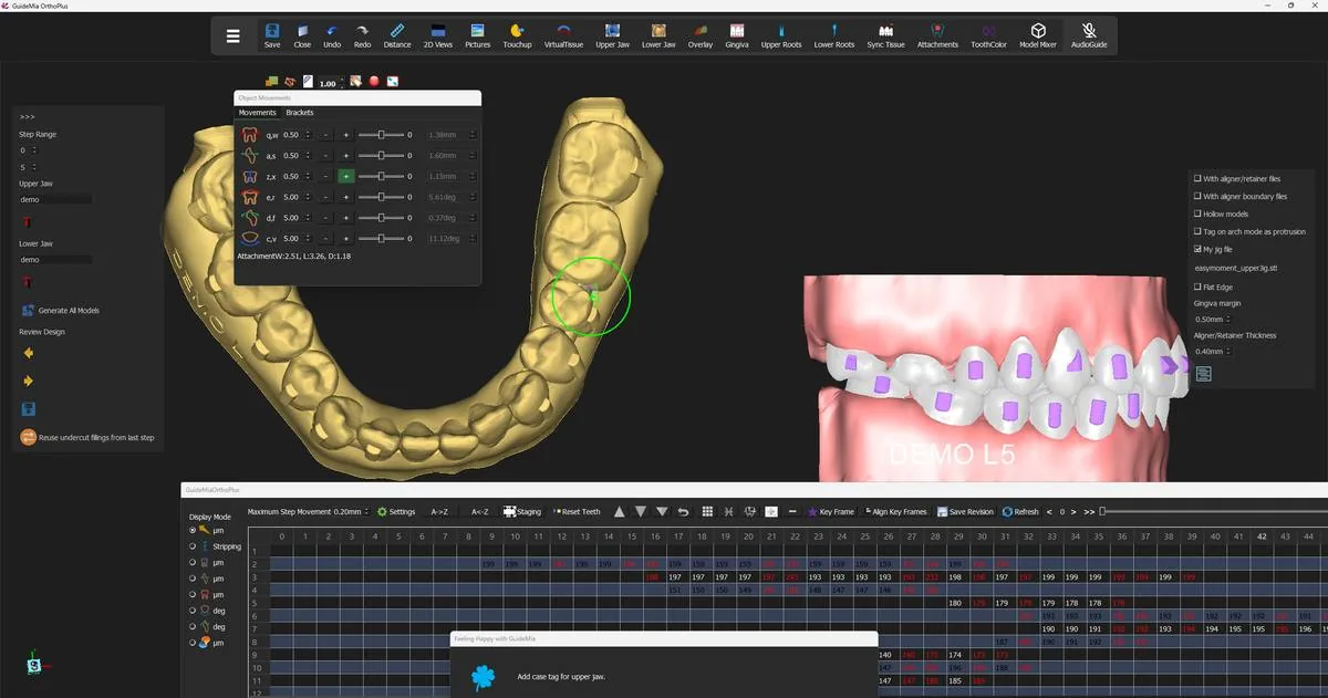
Walk the range. What you are looking for is the tag — legible, clear of the tooth area, in the same place on every model — and the interproximal regions, because that is where an arch model differs most from the arch it came from:

"You can edit the arch models in the reviewing process. Each model will come as multiple component: the base model, and the interproximal fillings. You can double click on a filling area, move it and resize it."

Those fillings are deliberate. A thermoformed sheet cannot follow a deep undercut between two crowns and will either tear or lock the aligner on, so GuideMia builds material into the embrasures. Turning the model to an occlusal view is the quickest way to see all of them at once; a filling that has grown too far up the crown is one you can double-click and pull back.

A generated lower arch model from the occlusal, with the interproximal fillings visible between the crowns. A generated lower arch model from the occlusal, with the interproximal fillings visible between the crowns.
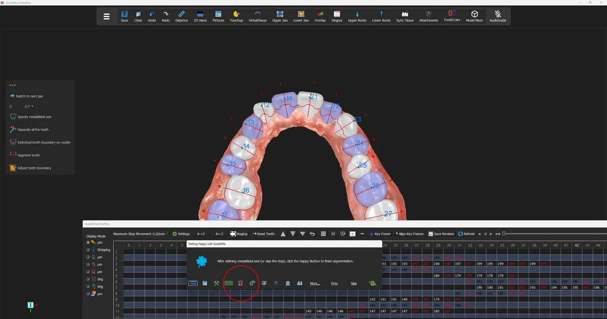
If you change a model, use the save button — "Save the current model or path file. If it has been changed, the system will save it in a different time." [sic] — before moving on, because the transport does not save for you.

If you are reviewing files from an earlier session rather than the ones you have just made, the file-selection button beside the review options points the transport at them:

"By default the system will automatically pick up the newly generated files. This file selection will let you pick files in different session. It does not prevent you from selecting files from other cases, but that does not make much sense, so be sure only select files for this case."

Where you are now

A folder holds an arch model for every step in the range, for both jaws, each one carrying the case tag and its own aligner number, each one with its interproximal fillings reviewed. That folder is what a thermoforming lab needs and nothing else in the project has to travel with it.

Two steps remain. Step 12 takes the same plan down the other path and generates the aligners themselves. Step 13 shares the case for review and saves the work.

More on this page

"Aligner or Model Design" and "Arch Model Options", beyond what the demo used:

ControlWhat it is for
"With aligner/retainer files"Switches the output from arch models to aligners — step 12
"With aligner boundary files"Also writes trimming paths, for automatic trimming
"Aggressively avoid collisions"Extra collision checking during generation; slower
"No attachments before movements"Omits an attachment until its tooth starts moving
"No attachments after movements" [sic]Omits an attachment once its tooth has arrived
"Undercut filling" — "Height factor", "Width factor"Governs the interproximal fillings
"First step only"One model, for verification; free on a metered licence
"Add/Remove base for printing"Adds a bar joining the molar regions, for printing models vertically
"Add expander" (upper only)Connects the middle of the upper arch, for expansion cases
"Generate First Set"Generates the first set rather than the whole range
"Reuse undercut fillings from last step"Carries the previous step's fillings forward
"GuideMia fixture"The default trimming fixture; selected unless you change it
"Ortho-automation fixture"A worked example of a customised jig
"My jig file" / "EasyMoment jig file"Your own jig STL, which must be in the right coordinate system
"Gingiva margin" (mm)Margin from trimming path to aligner boundary — "You should contact your supplier for this value."
"Posterior edge clearance" (mm)Lifts the trim at the back of the arch so aligners seat and release more easily
"Fill in undercuts and gaps"On by default; not recommended to turn off
"Hollow models" + thickness (mm)Hollows the model to save resin
"Tag on arch mode as protrusion" [sic]Tag raised when on, cut in as slots when off
"Tag on crown too"Adds a small aligner number to the first posterior tooth without an attachment

The fixture group is only meaningful when "With aligner boundary files" is on: the trimming paths are generated against the fixture file and the arch models are built with the fixture part attached, so choosing a jig you do not own produces models a trimmer cannot hold.

Step 12 of 13

Generating the aligner files

Direct-print aligners instead of arch models: the boundary, the printer-specific parameters, and the files that come out.

Everything up to here has produced arch models: a solid model of the jaw at each step, made so that a sheet of plastic can be drawn over it. GuideMia can skip that entirely and build the aligner itself — the shell, terminated at its gingival boundary, with a socket for every attachment — as a file you print directly. No model, no sheet, no trimmer.

The plan does not change. The tooth positions, the staging and the attachments you settled in steps 8 to 10 are the same ones the shells are built from. What changes is the object the generator produces, and the handful of settings that describe it: how thick the shell is, how it terminates between the teeth, and how much clearance your printer needs to make it fit.

Note the word for each thing, because the panel uses both and they are not interchangeable. GuideMia generates arch models and it generates aligners. Direct print describes what you do with the files afterwards.

The last look round before output

Part two of the recorded session opens with the operator doing something worth copying: stepping back through the earlier pages of the workflow and looking at the case one more time.

The row of small icons along the bottom of the Happy Button dock are destinations, not steps. They do not advance anything — they reposition the workflow, opening a page and moving the Happy Button to the step that belongs there, so the wizard and the display stay in agreement. The operator visits the system dashboard, then "Fix models", then "Tooth segmentation", then "Post processing for tooth segmentation", and finally "Model design".

Stepping back to the segmentation page; the Happy Button follows to the step that belongs there. Stepping back to the segmentation page; the Happy Button follows to the step that belongs there.
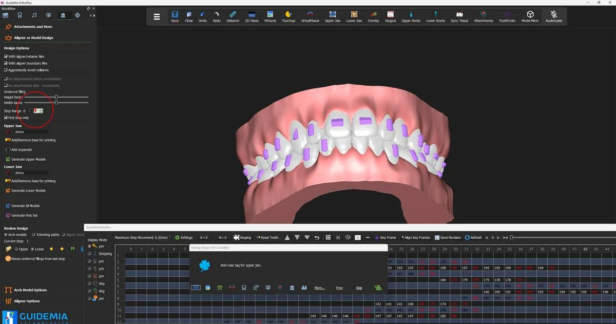
Nothing is undone by doing this. The models are as they were, the teeth are still segmented, the plan is still staged; you are reading, not editing, and returning to "Model design" puts the Happy Button back on "Add case tag for upper jaw." where you left it.

It is worth the two minutes because this is the last checkpoint. Once the shells are generated and sent to a printer, a boundary that runs through a crown or a tooth that was never properly separated becomes an appliance the patient cannot wear, and the cost of finding it here is a scroll and a glance.

While you are there, turn the analysis overlays off again — "Turn off buccal-libgual movement map" [sic], "Turn off bone density map" and "Turn off Occlusal Distance Map" from the right-click menu — since the pages you have just visited turn some of them back on.

The switch

One checkbox decides everything that follows. On "Aligner or Model Design", tick "With aligner/retainer files":

"This aligner and retainer option tells the system to create aligner or retainer models for direct printing, instead of arch models for thermoforming."

That single tick is the mode. The generate buttons do not change their names or their positions, so a run that produced arch models yesterday and aligners today differs only here — which is why it is worth checking rather than assuming. The setting is stored with the rest of the design configuration and survives between sessions, so a lab that works one way stays configured that way, and an occasional aligner case needs the box ticked deliberately.

Note the option covers retainers as well as aligners; the same pipeline produces both.

You will see two of the options above it go grey the moment you tick it. "No attachments before movements" and "No attachments after movements" [sic] are switched off and held off for the whole run. Their purpose is to save geometry on an arch model where an attachment is not needed yet, and on a printed shell the attachment is a socket rather than a saving. The optimisation does not apply on this path, so GuideMia removes it from your reach.

The design page in aligner mode: the aligner/retainer option ticked, the attachment-timing options greyed out. The design page in aligner mode: the aligner/retainer option ticked, the attachment-timing options greyed out.
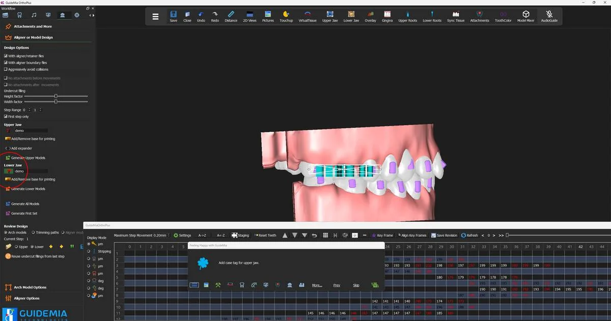
The four numbers that describe a shell

"Aligner Options" is the section that exists only for this path. Four controls, and a lab will ask about all four.

"Aligner/Retainer Thickness", in millimetres:

"Set the aligner/retainer thickness. The suggested range is from 0.5 to 3.5. Please be advised the final models can have different thickness in different areas."

The number you set is a target rather than a guarantee: as the note says, the finished models can vary in thickness from one area to another, so do not expect a measurement taken at two points on a printed shell to agree.

"Printer Clearance for Aligner Models", in millimetres, is the setting to get right before anything else:

"This parameter compensates the printer pixel size or layer thickness. It needs to be set according to printer specs. Typically this can be half to one pixel size."

This is the offset that makes a printed shell fit. It is a property of your printer, not of the case, and it is set from the printer's specification — half to one of its XY pixel size. If a first batch of printed aligners comes out uniformly too tight or uniformly too loose across every step, this number is the reason.

"Interproximal sharpness", in millimetres, shapes the edge:

"This parameter controls how the aligner models or the trimming paths will conform with the crown boundaries. The bigger the value, the less curved those models are. 3-4mm value would likely make the aligners have flat edges."

Small values follow the gingival scallop between the crowns; large values flatten it out. "Flat Edge" is the override — "This option will force the system to ignore the interproximal sharpness setting so the aligners or trimming paths have flat edges."

"Posterior edge clearance" lifts the edge at the back of the arch: "This will make it easier for the patients to put on and take off the aligners."

The boundary the shell terminates at

A printed aligner ends where the crown ends, and GuideMia calls that line the aligner boundary. Its own explanation of the name is the clearest statement of what it is:

"This function extracts the upper jaw aligner boundary, or, crown boundary. It is called aligner boundary because the individual crown boundaries are merged into a loop. After the boundary is generated, you can adjust it by dragging anywhere on the curve in order to follow the crown boundary better."

The boundary was established back in data preparation, and if it needed correcting this case, it was corrected there. It is worth naming here because it is the line the shell is cut at — anywhere the boundary sits above the true gingival margin, the finished aligner will be short, and anywhere it sits below, the aligner will press on tissue. Manual variants exist for both jaws ("draw the aligner boundary by specifying and connecting points. Go around the model and click on the first point to close the profile.") if a boundary needs redrawing rather than nudging.

Step range and case tag

Set "Step Range" the same way as for arch models. The recorded case runs a short range with "First step only" ticked, which is the verification shortcut described in step 11 and is worth using here more than anywhere else in the guide: print one shell, put it on the model, confirm it fits, and only then commit the range. On a metered licence that test costs nothing.

The case tag works the same way and lands somewhere different. Type the tag first — letters and numbers, no step numbers — then click "Add/Update Case Tag" to place it and click again to finish. GuideMia is explicit that this step is not the same in both modes: "The tag is added in different way for arch models or aligner models." On an arch model the tag sits out on the base, away from the teeth. On an aligner there is no base, so it goes on the shell itself, along the buccal surface where it can be read without taking the aligner out of its bag.

The case tag placed on the lower aligner, on the shell rather than on a base. The case tag placed on the lower aligner, on the shell rather than on a base.
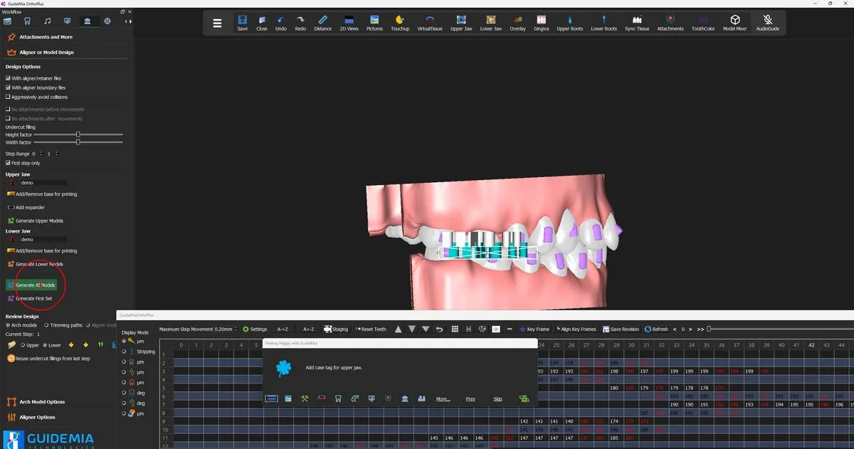
Then the upper, with its own field and its own placement.

Generating

"Generate All Models" — the same button, now producing shells:

"All the models within the given step range will be generated for the upper jaw. The function will ask for a file name. Typically you want to create a new folder to hold the files. When you give the file name, do not use aligner numbers."

New folder, no numbers in the name; GuideMia appends the step. As before, the plan is validated first and "OK" on the Plan Validation dialog is enabled only by the acknowledgement tick-box, so read the marked items before you confirm.

Generating the aligners for the step range. Generating the aligners for the step range.
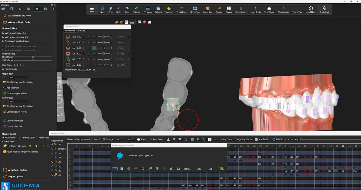
Several things that a thermoforming run needs are simply absent from this one, and their absence is correct rather than an omission:

  • No trimming jig and no trimming path. A printed aligner is already terminated at its boundary. There is nothing to trim, so there is no fixture to hold a model in a trimmer and no path to drive one.
  • No virtual soft tissue. An arch model is printed with gingiva so the sheet has something to wrap; a shell stops at the boundary and does not need it.
  • No hollowing and no printing base. Both are arch-model economics — resin saved on a solid model, and support for printing it upright. Neither applies to a shell, which is already hollow and already thin.

At an extraction site the handling differs too. GuideMia performs the extraction on the original tissue model at step 0 and restores the tissue for the rest of the run, and the option "Keep space for aligners" — "This option will set the extraction mode to partially remove the crown area." — leaves a pontic-like volume rather than a hole, so the shell has something to close over.

Reviewing the shells

The "Review Design" transport works exactly as it did for arch models: pick the jaw, then walk the set with the next and previous buttons while "Current Step:" tells you where you are.

What the transport shows you depends on what the run generated. The recorded case ticks both "With aligner/retainer files" and "With aligner boundary files", so the boundaries are written alongside the shells and you can choose to view them — select the boundaries and walk the same set to see the edge each shell was cut to, which is the quickest way to check a margin you are unsure about against the curve that produced it.

A generated aligner in the working window, with its case tag and an attachment socket selected. A generated aligner in the working window, with its case tag and an attachment socket selected.
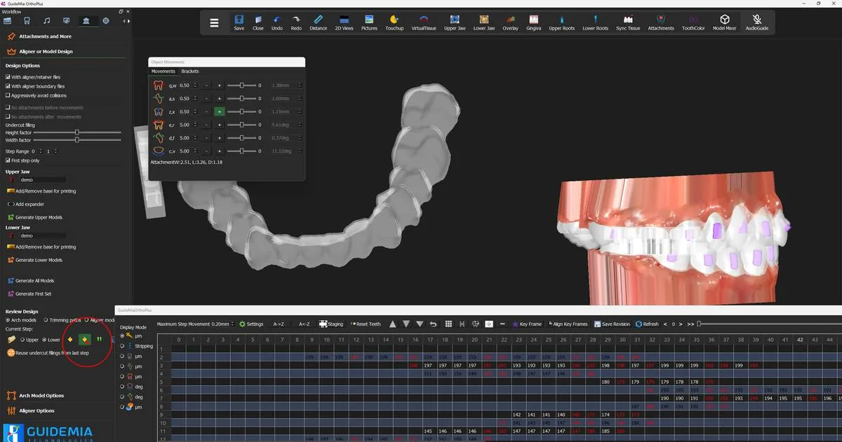
What to look at, in this order:

The sockets. Every attachment on the tooth should have a matching pocket in the shell, with a clean wall around it. A socket is the feature most likely to show a defect, because it is where the shell has the most geometry to follow.

The margin. Turn the model to the occlusal and follow the edge all the way round both sides. It should run parallel to the gingival line at a consistent height, scalloped or flat according to how you set the interproximal sharpness, and it should not dip below the crown anywhere.

The tag. Legible, on the buccal, in the same place on every step.

The same aligner from the occlusal, showing the margin all the way round the arch. The same aligner from the occlusal, showing the margin all the way round the arch.
Step past the last file in the set and GuideMia says so:

"File not found" — "No more file to edit."

That is the end of the range, not a fault. Click OK, switch jaws, and walk the other side.

The end of the review set for one jaw. The end of the review set for one jaw.
Where you are now

A folder holds an aligner for every step in the range, for both jaws, each one tagged and numbered, each one carrying the sockets for the attachments on the teeth it covers. Those files go to a printer as they are.

Two matters sit outside this guide and should go to GuideMia rather than be guessed at: resin selection and post-processing, which are a regulatory question and not a software one; and whether your licence covers aligner design for printing, which is an entitlement question — see the licensing guidance.

More on this page

"Aligner Options", and the controls on the design page that behave differently once "With aligner/retainer files" is ticked:

ControlWhat it is for
"With aligner/retainer files"The mode switch: aligners instead of arch models
"Aligner/Retainer Thickness" (mm)Target shell thickness; 0.5–3.5 suggested, and it varies across the shell
"Printer Clearance for Aligner Models" (mm)Set from your printer's spec — half to one pixel size. This is the fit
"Interproximal sharpness" (mm)How closely the edge follows the crown boundaries; 3–4 mm gives flat edges
"Flat Edge"Overrides interproximal sharpness and flattens the edge outright
"Posterior edge clearance" (mm)Lifts the edge at the back of the arch for easier seating and removal
"Upper jaw aligner boundary" / "Lower jaw aligner boundary"Extracts the boundary loop; drag the curve to adjust
"Manual upper jaw aligner boundary" / "Manual lower jaw aligner boundary"Draw the boundary point by point; click the first point to close
"Keep space for aligners"Partial crown removal at an extraction site, so the shell has volume to close over
"Aligner models" (Review Design)Reviews the generated shells; available only in this mode
"First step only"One shell for verification; free on a metered licence
"Tag on crown too"A small aligner number on the first posterior tooth without an attachment

The arch-model controls stay on the page and stay inert: the fixture choice, "Gingiva margin", "Hollow models" and "Add/Remove base for printing" all belong to the thermoforming path, and a shell run passes them by.

Step 13 of 13

Delivery — web review and saving

Package the case for review in a browser, share it, and save the project and its revisions.

The files exist. What remains is getting the case in front of whoever has to approve it, and making sure the project you spent the last twelve steps building is still there tomorrow.

Both are done from the system menu — the button at the left of the toolbar, which opens "the full GuideMia menu with every Project / Edit / View / References / Tools / Account / Help / ProjectType entry."

Sending the case out for review

Project → "All files for Web Review" packages the case for someone else to look at:

"This generates a package of file for online review. It can only be reviewed on GuideMia's portal. You are recommended to use the tool under gTok menu."

Two things follow from that. The package is for GuideMia's portal, not for a generic 3D viewer — the reviewer opens it in a browser and gets the case, not a folder of meshes to work out for themselves. And GuideMia would rather you sent it through gTok, which handles the transfer and the contact list for you.

This is the step to use when a doctor has to sign off a plan before a lab commits to printing. The reviewer does not need GuideMia installed and does not need the project file, which means the plan can be approved without the working copy leaving your machine.

Packaging the case for online review from the Project menu. Packaging the case for online review from the Project menu.
You may have already met this offer. If you drove the design with the Happy Button rather than the panel, GuideMia asks at the end of the last generate step:

"Web Review" — "Do you want to save files for web review?"

Yes produces the same package. Answering No costs nothing — the menu entry is still there afterwards.

Saving the project

Project → "Save", or the Save button on the toolbar. It saves the current project: the scans, the segmentation, the roots, the plan, the staging, the attachments and the tags.

Saving the finished project. Saving the finished project.
Save at this point even though the models and aligners are already written to disk, because they are two different things. The STL files are output; the project is the case. Reopening the project is what lets you come back in six weeks, change one tooth and regenerate from step 20 — and without it, all you have is a folder of geometry no-one can revise.

Three neighbours in the same menu are worth knowing before you need them:

  • "Save Revision" stores the current plan as a named revision. A plan here means the tooth positions plus the attachments, and saved revisions are listed against the case, so you can keep a plan you are unsure about beside the one you sent out and switch between them from the Data Preparation page.
  • "Save for Transfer ..." prepares the project to go to another machine.
  • "Save As ..." writes it under a new name, leaving the original untouched — the safe way to start an alternative plan on the same case.

The record of the session

The recorded case ends where this guide began: Help → "End documenting".

"Start documenting" and "End documenting" bracket a session and produce a step-by-step record of it — every tool used, what GuideMia said about it, and a picture of the screen with the click marked. It is how the recording behind this guide was made.

It is worth knowing about for two reasons that have nothing to do with writing manuals. A case that went wrong somewhere and needs GuideMia support is far easier to diagnose from a documented session than from a description of one. And a technician being trained on a workflow can be handed a document of the case they just watched, rather than notes.

Ending the session record from the Help menu. Ending the session record from the Help menu.

Where you are now

The case is finished. Two optical scans became segmented arches, a set of target positions, a staged sequence of movements, an attachment set, and a folder of files a lab can put on a printer. The project is saved, and the plan is out for review.

More on this page

The "Project" menu carries more than the demo used:

EntryWhat it is for
"Load Models"Bring model data into the project
"Open"Open an existing project
"Save"Save the current project
"Save Revision"Store the current tooth positions and attachments as a named plan
"Save for Transfer ..."Package the project to move to another machine
"Save As ..."Save under a new name, leaving the original untouched
"Close"Close the project
"All files for Web Review"Package the case for review on GuideMia's portal
"Export Tooth Positions as XML file"Write the tooth positions out on their own
"Import Position XML File"Read tooth positions back in
"Export STL file"Export a model as STL

And from "Help":

EntryWhat it is for
"Start documenting" / "End documenting"Record the session as an illustrated step-by-step document
"Check for Updates"Look for a newer release
"Language"Change the interface language
"Reset window layout"Put the docks and windows back where they started
"Install or Update AI Engine"Install or refresh the engine behind the automatic tools
"Import bracket files"Load a bracket configuration file
"About"Version and build information

The export entries are the escape hatch when a case has to move between systems. "Export Tooth Positions as XML file" takes the plan out as coordinates rather than geometry, and "Import Position XML File" brings one back, which is how a plan produced elsewhere is brought onto a case that already has its scans and segmentation here.

Written from the GuideMia OrthoPlus Quick Start Guide V8.0 and the software's own interface definitions. Every indented quotation is a control's own status tip, taken from the source rather than paraphrased — including the software's own typos, marked [sic].

The toolbar layout and the icons differ between releases. Where a control is not where a figure shows it, look for it by name on the workflow panel, or open the system menu, which carries every entry regardless.