
A tooth-supported guide seats on teeth and stays where it is put. A full-arch guide on an edentulous ridge has nothing to hold it: it sits on compressible mucosa, it is long enough to rock, and every drill that passes through it pushes it. Anchor pins are what fix it to the bone.
This case uses three.
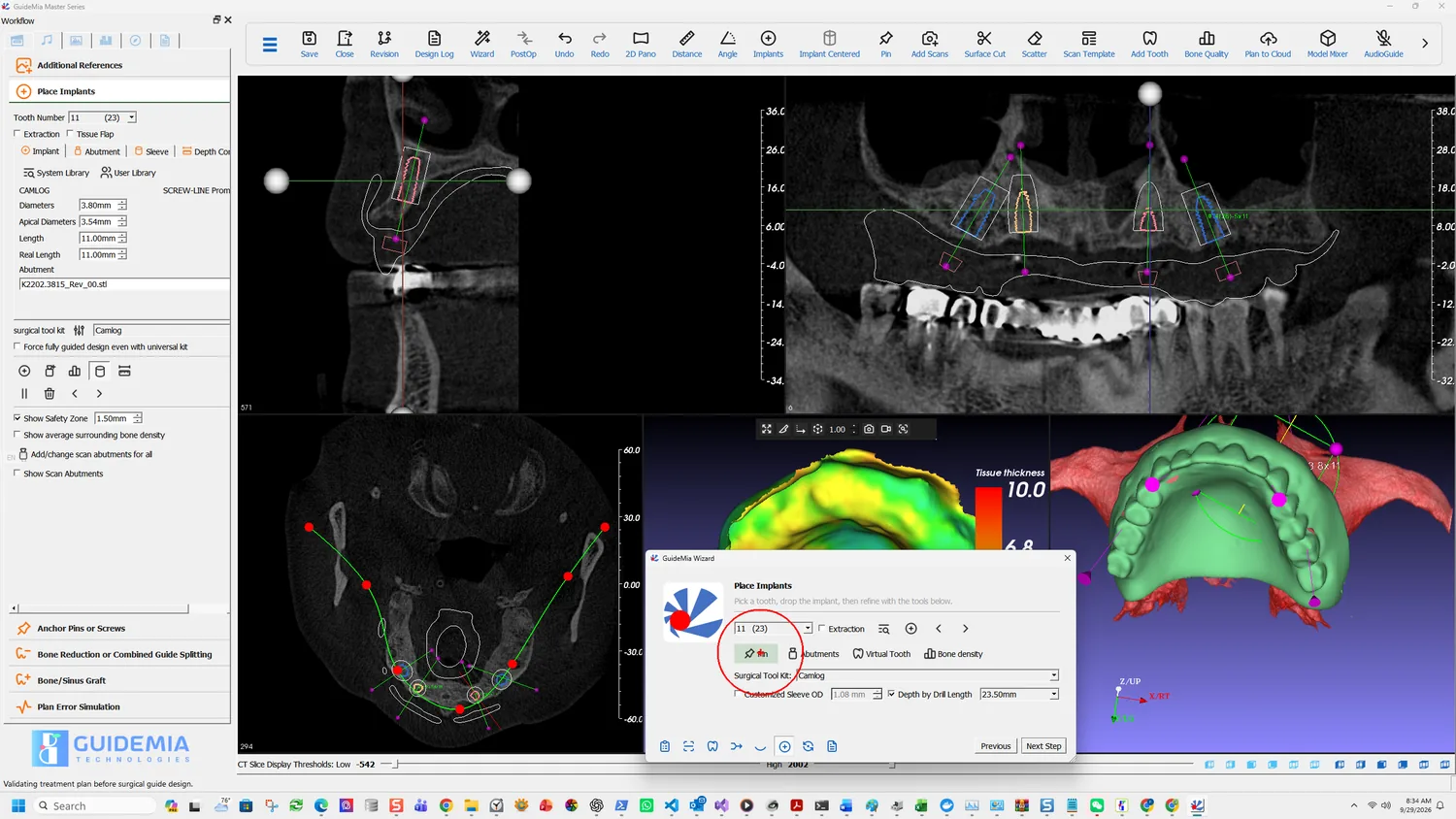
Placing one
Pin is on the Wizard's Place Implants page and on the toolbar, and the mechanic is the same as placing a fixture:
Add an anchor pin by clicking the desired site in any of the image windows, and then you can move and rotate the anchor pin. When the pin is too close to implants or other pins, it will turn red.
Click a site in any window — 2D or 3D — then move and rotate it as needed.
The red warning is the whole safety mechanism of this step, and it is worth stating plainly because it is passive: nothing stops you, nothing warns in words. A pin too close to an implant or to another pin simply changes colour. If you are placing three pins around four fixtures while rotating the view, that is easy to miss.
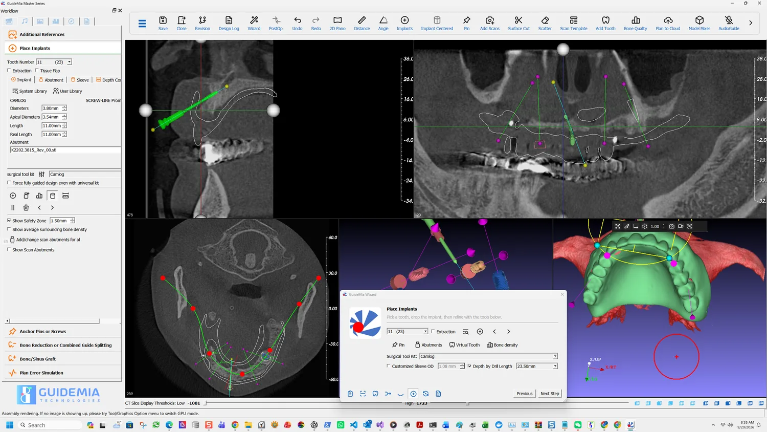
Where they go
The pins have two jobs and they pull in slightly different directions.
Hold the guide down. That argues for spreading them as widely as the guide allows — anterior and both posterior ends — because a guide pinned only at the front rotates about that point, and rotation at the front is displacement at the back, where the longest fixtures usually are.
Stay out of the way. Each pin needs bone to engage, clearance from every fixture and every sleeve, and a path that the surgeon can actually reach with the guide seated.
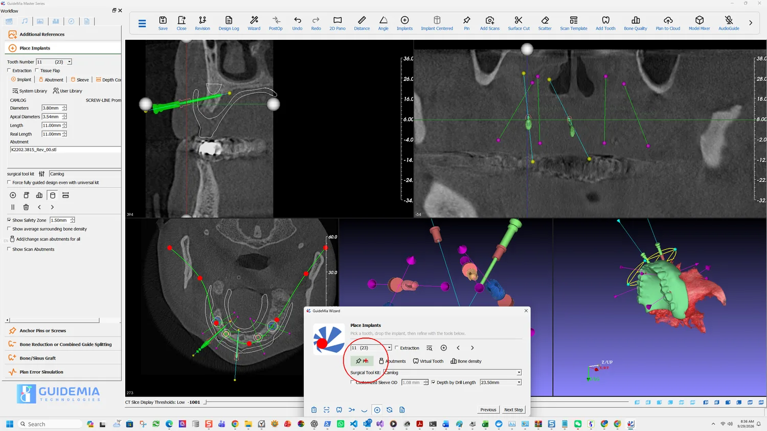
The parameters are on the right of the Place Implants page, and they are set before you place rather than after:
- Anchor Pin Diameter — 1.50 mm here
- Anchor Pin Length — 20.00 mm
- Update current anchor pin applies a change to the pin you have selected
Twenty millimetres is long, and deliberately so: a pin has to pass through the guide, through the mucosa, and far enough into bone to resist the drilling.

What the guide does with them
The pins are not an annotation. Generating the surgical guide puts a hole through it for each one, dimensioned to the pin diameter you set, which is why the parameters have to be right before the guide is built rather than after.
They also reach the report. The plan carries an Anchor pins section with a count, so the surgery knows how many to have ready and at what size — see export, save and report.
The sequence at surgery
Worth being explicit about, because the order is not obvious from the software: the guide is seated, the pins are placed through it to fix it, and only then is anything drilled. A pin placed after drilling has begun is fixing a guide that has already moved.
Anchor Pins or Screws is a page of its own on the workflow panel, beyond the Pin button the Wizard exposes. Screws are the alternative fixation where a pin will not serve.
The right-hand panel on the same page also carries the sleeve dimensions the guide will be built to — Sleeve Thickness 0.68 mm, Sleeve Length 5.25 mm and Sleeve Flange Thickness 0.90 mm in this case, following the Camlog kit. Those are the numbers customising a kit sets for a kit of your own.