
GuideMia ships with a long list of manufacturers, and Browse in implant placement reaches all of them. When the implant you use is not among them, you add it yourself — and once it is in, it behaves exactly like a shipped one.
This page covers both routes: adding implants with their geometry, and adding them as parameters only.
Two kinds of entry
Parameters only. An implant defined by its dimensions — platform diameter, apical diameter, catalog length, total length. The software plans with it, sizes the sleeve from it, and drives the guide from it. What you do not get is the fixture's real shape in the 3D views.
With STL geometry. The same parameters plus the actual model of the fixture, and optionally its abutments. This is what you want if you judge plans in 3D or use positioning by abutments.
If you are only adding parameters, skip straight to Adding them in the software below. Everything in between is about preparing geometry.
Where the files go
Two options, and the second is the one to prefer if you ever reinstall.
Option 1 — inside the installation. Find the GuideMia installation folder, typically:
C:\Program Files\GuideMia\GuideMia Master Series 64Bit\ImplantLibrary
Create a folder under it named for your catalogue — this page assumes
MyImplantLib.
Option 2 — outside it. Set the system environment variable
GuideMiaImplantLibraryDir to a folder of your own, for example
c:\AdditionalImplantLib, and create MyImplantLib under that.
Option 2 survives reinstalls and upgrades, and it can sit on a shared drive where several workstations read the same library. Option 1 is simpler and will be wiped by a clean reinstall.
Getting the coordinate system right
This is the part that decides whether your implant plans correctly, and it is entirely a question of how the STL is positioned before it ever reaches GuideMia. The software does not reorient what you give it.
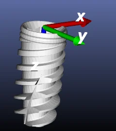
Four rules, and all four matter:
Z points to the tip. If the implant's catalog length — not its real
length — is L, the tip of the implant sits at (0, 0, L/2).
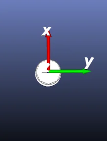
Y is the connector orientation, running from the buccal to the lingual side.
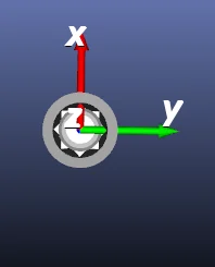
X follows from the other two.
The origin is at the centre of the connection plane.
That last one is where the three implant families differ, and it is worth understanding rather than copying.
Insertion length
The distance from the apical centre of the implant to the origin is the insertion length. For most implants, that is simply the length of the implant — origin at the top, tip at the bottom, done.
Subcrestal implants
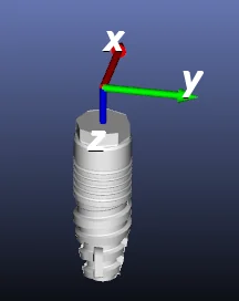
Some implants are designed to be placed below the crest. For these, the insertion length — also called the intra-osseous length — is the implant length plus the level of placement. The manufacturer publishes that level value; use theirs rather than deriving one.
The visible consequence is that the origin sits above the top of the fixture by exactly that amount.
One-piece implants
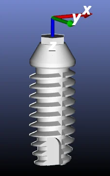
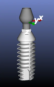
For a one-piece implant there is no connection plane in the ordinary sense.
The origin is not at the top; it depends on the catalog length, by the
same (0, 0, L/2) rule applied to the catalog figure.
Abutments
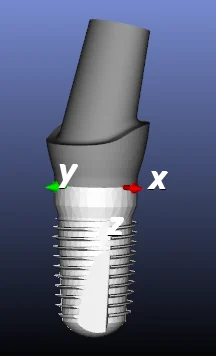
Abutment STLs go in the same coordinate system, with three requirements:
- Z is the same direction as the implant's Z.
- X and Y are placed so the connector aligns with the connector in the implant — the hex, or whatever the system uses. As with the implant, Y runs buccal to lingual.
- The origin is at the same position as its compatible implants.
Get the second one wrong and the abutment will appear rotated relative to the fixture, which shows up immediately in the 3D view.
Copy every STL — implants and abutments — into the folder you created.
Adding them in the software
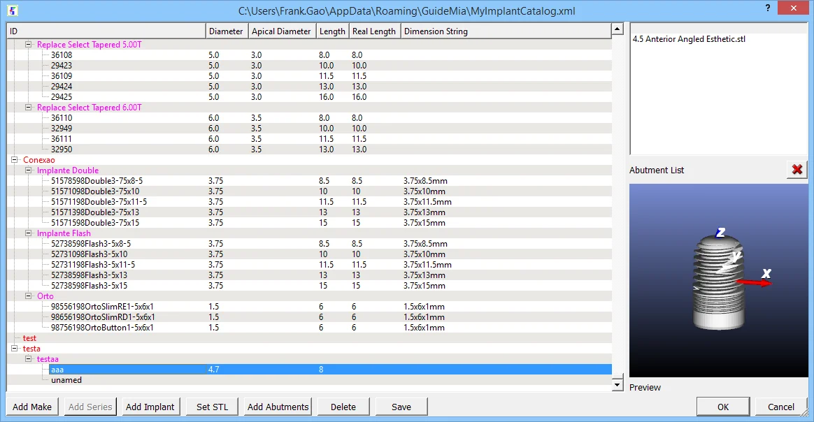
Start GuideMia and open the implant library management dialog. It lists your catalogue as a tree of makes, series and implants, with the columns that matter for planning: ID, Diameter, Apical Diameter, Length, Real Length and Dimension String. A Preview panel shows the selected implant with its axes drawn, which is the fastest way to confirm you got the coordinate system right, and an Abutment List shows what is attached to it.
The buttons across the bottom are the whole workflow:
- Add Make — the manufacturer. Name it
MyImplantLibto match the folder. - Add Series — a product line within that make.
- Add Implant — one fixture. Type in its parameters.
- Set STL — select the corresponding STL from the files you prepared. Skip this if you are adding parameters only.
- Add Abutments — select the abutments compatible with this implant. You can select several at once.
- Save — and repeat from step 3 for the next implant.
Click Save again after the last one. Your implants are now in the library and appear under Browse during planning.
The title bar of the dialog shows where your additions are written, which is worth noting for backups:
C:\Users\<you>\AppData\Roaming\GuideMia\MyImplantCatalog.xml
That file is yours. It is separate from the shipped catalogue, and it is what to copy when you move to a new machine.
Asking GuideMia to add them for you
If you would rather have your implants in a future release than maintain them locally, support will add them. Send the STL files together with a catalogue file in this format:
<implantcatalog version="1.0" name="CAT1">
  <implanttype version="1.0" type="0" id="i0" name="CAT1 Series1">
    <implant abutmentFiles="|3.5 Anterior Angled Esthetic.stl|3.5 Anterior Straight Esthetic.stl|3.5 X 2mm Straight Multi-Unit.stl|"
             id="InclusiveTapered3.7x8">
      <PlatformDiameter>3.7</PlatformDiameter>
      <OcclusalDiameter>3.7</OcclusalDiameter>
      <CatalogLength>8</CatalogLength>
      <ApicalDiameter>3.5</ApicalDiameter>
      <TotalLength>11</TotalLength>
      <IntraOsseousLength>11</IntraOsseousLength>
    </implant>
    <implant id="C1062.33010">
      <PlatformDiameter>3.3</PlatformDiameter>
      <OcclusalDiameter>3.3</OcclusalDiameter>
      <CatalogLength>10</CatalogLength>
      <ApicalDiameter>2.96</ApicalDiameter>
      <TotalLength>10</TotalLength>
      <IntraOsseousLength>8.6</IntraOsseousLength>
    </implant>
  </implanttype>
</implantcatalog>
Reading it: name on implantcatalog is the brand. Each implanttype
is a series — duplicate the whole block for each one. Each implant is a
fixture, and abutmentFiles lists the abutment STLs compatible with it,
pipe-separated with a leading and trailing pipe.
One rule that will silently break the import if you miss it:
Implant STL filename has to be same as its id name with extension ".stl".
So id="InclusiveTapered3.7x8" requires InclusiveTapered3.7x8.stl. The
second implant in the sample has no abutmentFiles and no STL — parameters
only, which is a valid entry.
Note the difference between CatalogLength and TotalLength in the first
entry — 8 against 11 — and IntraOsseousLength matching the total. That is
the distinction the coordinate-system rules above depend on, expressed in the
file.
Why the numbers have to be right
An implant you add drives more than its own picture. The surgical kit is matched against it, the sleeve is sized from it, and the drilling instructions printed on the report come from it. The Instructions For Use are direct about what a mismatch costs:
Combining instruments, surgical kits, and components that are not configured or dimensioned for correct mating can lead to mechanical failure of components, damage to tissue, or unsatisfactory aesthetic results.
And drill lengths in particular do not always mean what they appear to:
In some instances, drill length reference lines measure longer than the stated length of the implant.
Take every figure from the manufacturer's own catalogue, and check a new entry against a known case before you plan a patient on it.
Related
- Customising the surgical kit — the sleeves and drills the guide is built around
- Placing the implant — where the library is used
- The GuideMia surgical kit