
The plan becomes an object here. The Wizard reduces it to three acts — "Set insertion direction, outline the guide, then generate" — and the status bar names what happens underneath: "Validating treatment plan before surgical guide design." The plan is checked before any geometry is built.
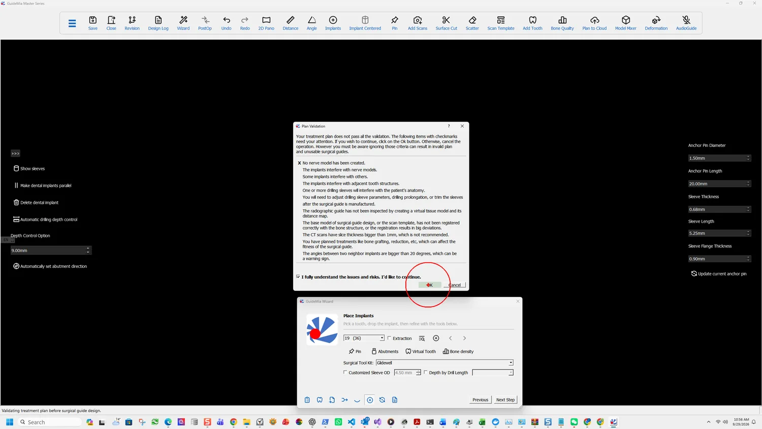
Set the insertion direction
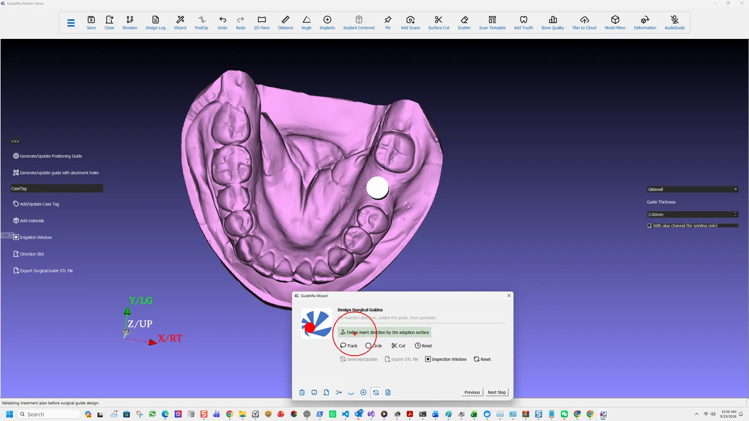
Define insert direction by the adaption surface takes the direction from how you are looking at the model. Its status tip is four words and they are the whole mechanic:
Update insert direction as view normal
So orient the view the way the guide will seat, then click. There is no numerical entry and no separate dialog; the camera is the input.
Getting it wrong does not fail immediately. It surfaces two steps later, when Cut returns the occlusal side of the model instead of the gingival one, and the cause is not obvious from the symptom.
Outline the guide
Two tools do the same job by different means. Both work from a bone model or an optical scan; neither is for radiographic guides.
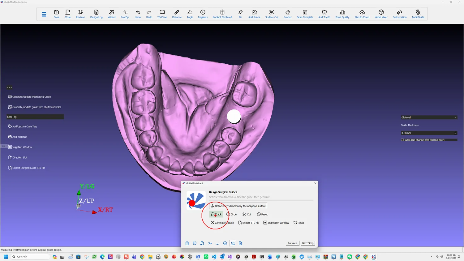
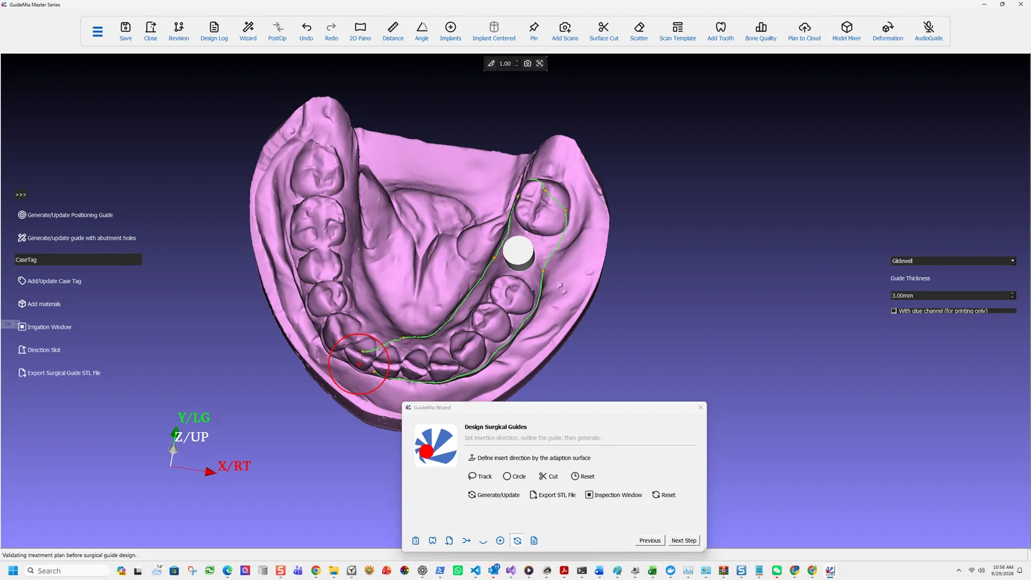
Track is the usual one. Select points on the base model and they connect into a boundary; click the first point again to close it. Two handling notes, both easy to trip over:
If you even need to rotate the view, move your mouse out of the model area and then rotate using the left button. Do not use right mouse button during the process. If you do so, it will stop, you can click the button again to redefine the boundary.
So: rotate only from outside the model, and never right-click. Right-clicking abandons the boundary and you start it again.
Circle is the alternative for when Track will not cut. It draws a profile on the display plane, and the direction you draw in is meaningful:
When you draw the profile clockwise, the area within the profile will be kept. If you go anti clock wise, the circled area will be trimmed away.
Expect to work in passes with it — define a profile, Cut, rotate, cut again.
Cut
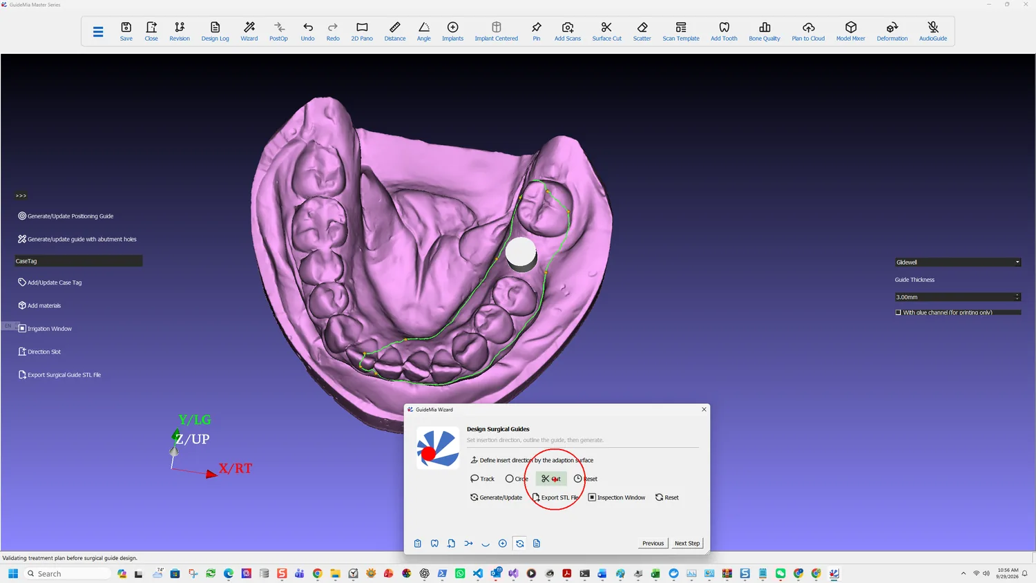
Cut applies the boundary, selecting the area inside it. Three outcomes and what each means:
It selects the right area. Carry on.
It selects the wrong side. Take the alternative area with the button to its right, rather than redrawing.
It fails. The software points at the cause:
If this operation fails, you need to consider fix the base model or use the Circle tool. If an optical scan has quality issues, small holes, etc, this operation may fail. Go back to planning mode, right click on the scan template model to fix it.
A scan defect that was invisible at registration shows up here. This is the same fault described in registering the scan — which is why looking at the scan before registering it is worth the minute.
Reset clears the guide base definition so it can be defined again.
Set what the guide is made of
The panel on the right decides the physical object rather than its outline:
- The implant system the sleeves must match — Glidewell in this case, following the surgical kit set during planning.
- Guide Thickness — 3.00 mm here.
- With glue channel, which is for printing only.
The sidebar carries the variants and the finishing work: Generate/Update Positioning Guide, Generate/update guide with abutment holes, Add/Update Case Tag, Add materials, Irrigation Window, Direction Slot and Export Surgical Guide STL File.
Generate
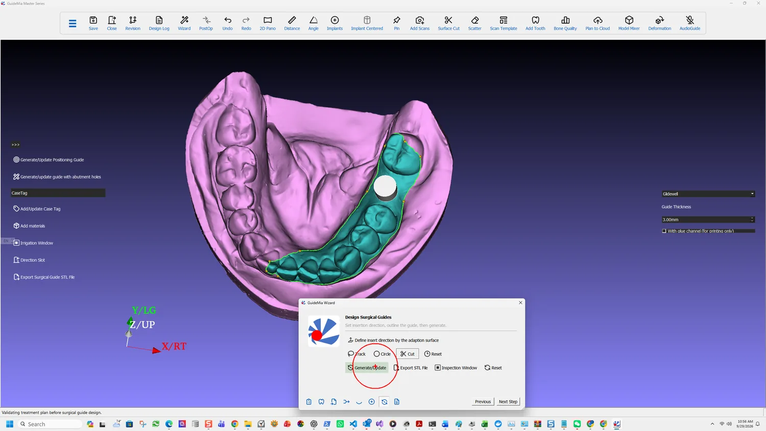
Generate/Update builds the guide — and it is also how you revise one:
In case the guide base has been defined, and you go back to the planning page to adjust Dental Implant positions or other options, you can come back here and click to update guides. This function works for all the surgical guide types. In case of bone reduction guides, plateau guides and combined guides, this will generate all guides together.
That is the sentence worth remembering: the outline survives a change of plan. Move an implant, come back here, update. You do not re-trace the boundary.
And for a case with several guide types, one click generates them all rather than each in turn.
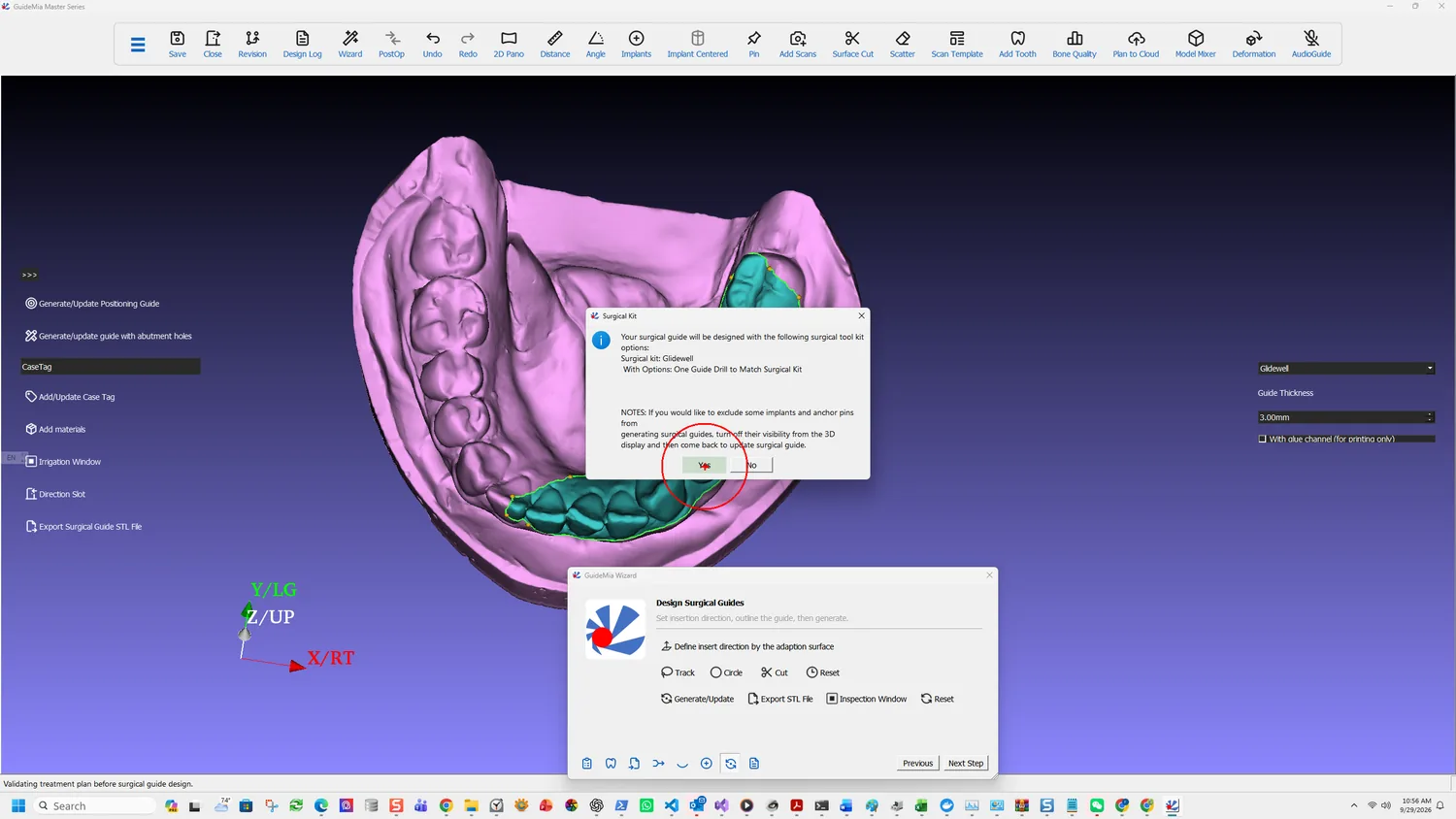
The Surgical Guide Design group in the workflow panel carries what follows generation:
- Post Processing — the finishing operations applied to a generated guide.
- Master Model — for producing a model alongside the guide.
- Split Guides for Full Arch — dividing a full-arch guide into sections that can be printed and seated. Not relevant to a single unit; essential when the span is long.
- Surgical tool kit and Guide Options — the same kit and sleeve parameters reachable from planning, so a guide option can be revised without going back.
Guide types beyond the ordinary one, all generated by the same button: positioning guides, guides with abutment holes, bone reduction guides, plateau guides, hybrid guides and tooth-supported guides. The tooth-supported route is the CT-only case described in choosing the case type — on entering guide design the system asks whether to design a purely tooth-level guide, and answering yes builds clearance cylinders between the guide and the bone and tooth model so the guide seats on the neighbouring teeth.