
A guide can be geometrically correct and still not seat. Fit analysis is the check that separates the two, and it is the last thing worth doing before a case leaves the software.
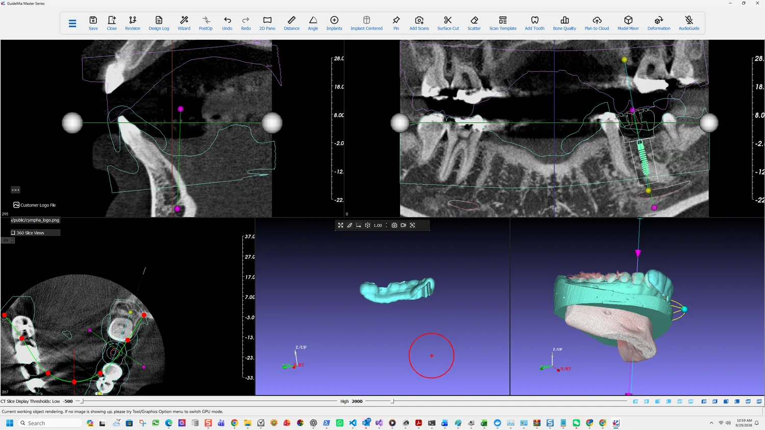
What it actually measures
The manual is precise about this, and the precision matters for reading the result:
The idea is to calculate the deviations between the surgical guide and patient's anatomy, and visualize them. The "distance" is between a point on the surgical guide and the model that is used as the base for surgical guide design, such as a stone model for tissue-based guide or bone model for bone-level surgical guide.
So it compares the guide against the model it was designed from — in this case the registered intra-oral scan. That has a consequence worth stating plainly: fit analysis validates the geometry of the guide against the scan, not the scan against the patient. If the registration in step 5 was poor, fit analysis will show a beautiful result and the guide will still not seat.
Which is exactly why the manual lists it where it does — under improving the model registration. It is a visual tool for finding registration problems, and a clean map over an area you expected to be clean is evidence the registration held there.
Turning it on
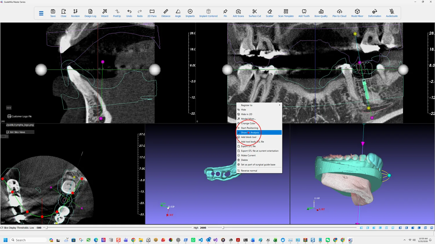
Right-click the guide in the assembly window and choose Show Fit Analysis. It sits on the same object menu as Register to, Hide, Model Mixer, Change Color, Start Positioning, Make Current and the export entries — an object-level operation rather than a workflow step, which is why it does not appear in the Wizard.
Reading the map
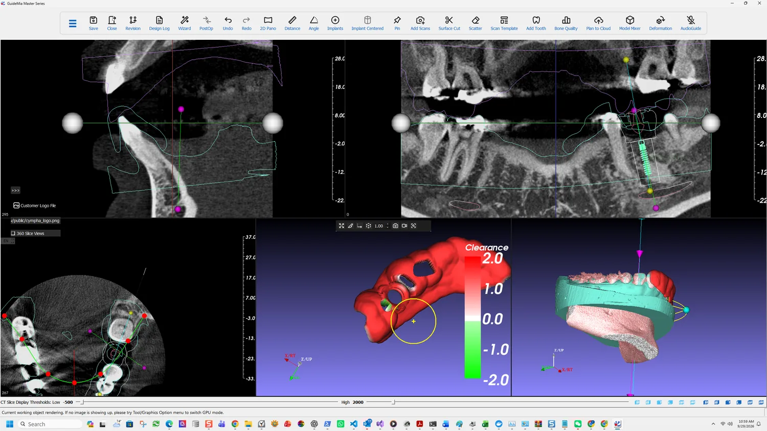
The guide is recoloured and a Clearance scale bar appears beside it, running from +2.0 at the top through 0.0 in the middle to -2.0 at the bottom. The scale bar is the whole instrument — it defines how distance maps to colour, and the numbers are millimetres.
- Green — negative clearance. The guide is closer to the base model than the nominal surface, or intersecting it. On a tissue-borne guide this is the side that will not seat: material has to go somewhere, and if it cannot, the guide rocks or sits high.
- White — zero. Contact.
- Red — positive clearance. A gap. Some is designed in; a large one over an area meant to provide support means that area is not providing it.
The case here reads red across the fitting surface, which is what a tooth-supported guide with designed relief looks like. What you are hunting for is local variation rather than an overall shade: a patch that differs from its surroundings is a feature of the scan or the design, and that is what to go and look at.
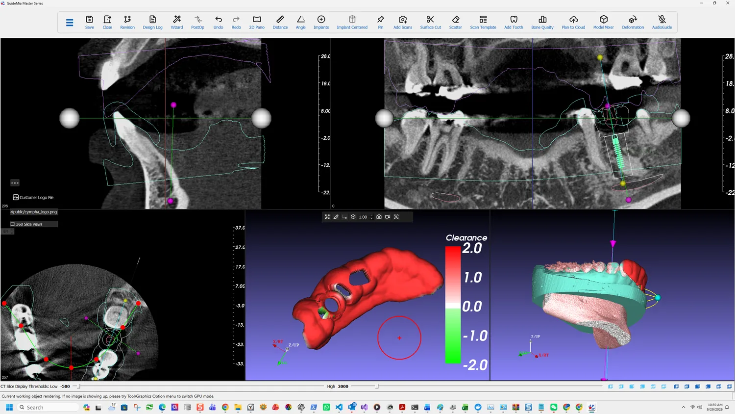
Rotate through the whole fitting surface rather than judging one view. The areas that decide seating are the ones furthest from the implant site, because that is where a rotation shows up first — the same logic that governs where inspection windows go.
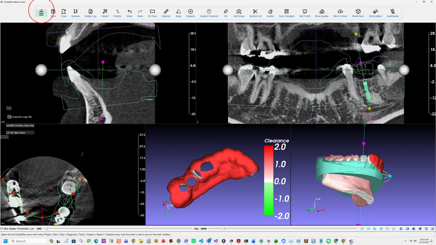
The underside is the surface that meets the patient, so it is the one the analysis is really about. Here the sleeve hole and the inspection window are both visible in the map, and the margins around them are worth a look: a window cut close to a support area removes support from it.
What to do about what you find
A local green patch — the guide intersects the base model there. Check whether the scan has a defect at that spot; this is the same class of fault that makes Cut fail in guide design.
A large red area over an intended support — that region is not carrying the guide. Either extend the outline onto something that will, or accept it and rely on the remaining support, knowingly.
A map that disagrees with what you expected everywhere — suspect the registration rather than the guide, and go back to step 5.
The manual pairs fit analysis with one other remedy, and it is the one to reach for first: fine tuning. After registration you can slightly move or rotate the model so it better matches the patient anatomy. Fit analysis tells you which way.
And then the physical check
Fit analysis is a digital check against a digital model. It does not replace the one the Instructions For Use require:
The applicability of the surgical guides must be verified before the surgery... This includes trying the model onto diagnostic models, and on patient's anatomy. If a guide is found not fit properly on the patient's anatomy, or cannot be properly secured, it must not be used for the treatment.
Nor does the exported STL leave the software as a finished device — the guide must be finished with drilling sleeves before it is used. See intended use and safety.
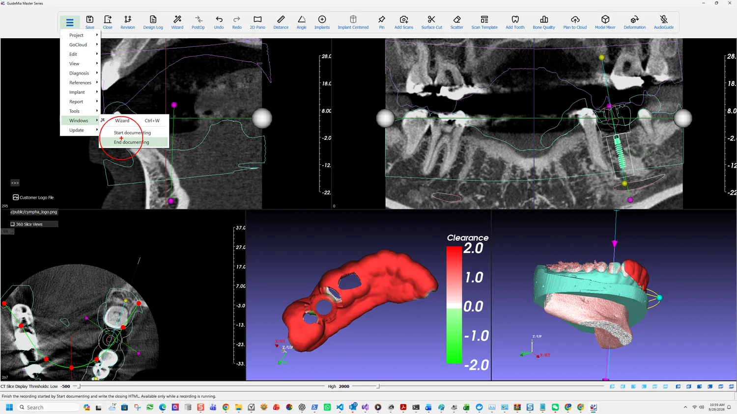
The hamburger at the left of the toolbar opens the full system menu, and its status tip is the sentence to remember when a function in this guide is not where a figure shows it:
Open the full GuideMia menu with every Project / Edit / View / Diagnosis / Tools / Implant / Report / Update entry. Use this when a tool is not on the main toolbar.
That is the answer to most version differences. The toolbar and the icons change between releases; the menu carries everything regardless.