
Front matter
Intended use and safety
What GuideMia OrthoPlus is and produces, its indications for use, intended users, warnings, and the boundary between what the system does and what remains the clinician's judgement.
What GuideMia OrthoPlus is
GuideMia OrthoPlus is a Windows desktop application for orthodontic treatment planning and appliance design. It takes intra-oral scans — and, where you have one, a CBCT volume — separates the individual teeth, produces a treatment plan, stages the movement into steps, and writes out files you can manufacture from.
Everything happens in one program, on your own machine, in one project file. There is no separate module to launch, no intermediate file to hand between tools, and no second application to install. Segmentation, planning, staging, attachments, model generation and reporting are all pages of the same workflow, and the case carries all of them. If you have the case open, you have everything open.
Projects are saved with the extension .gos; a packaged project, the form you send to someone else, is .gos.gpk.
What the software produces:
| Output | Used for |
|---|---|
| Arch models, one per step | Printing, then thermoforming aligners over |
| Aligner and retainer shells | Printing directly, no thermoforming |
| Aligner boundary files | Reviewing and adjusting the cut line of each shell |
| Aligner trimming paths | Driving a robotic trimmer |
| Bracket bonding guides | Indirect bonding of fixed appliances |
| A combined model of teeth, gums and attachments | Visualisation and case sharing |
| A treatment report | Presenting the plan |
Two strengths are worth knowing about before you begin, because they change how you work. The first is that automation is offered at every stage rather than in one place: the Happy Button described in step 1 will do the next step of the workflow for you at any point, and AlignerBot will run a whole case end to end. The second is that everything runs on your own machine. Cases are not uploaded for processing, and the AI Engine that performs segmentation is a local program.
Indications for use
"GuideMia Ortho+ software system is intended for use as a medical front-end device providing tools for management of orthodontic models, systematic inspection, detailed analysis, treatment simulation and virtual appliance design option (Custom metal bands, export of models, Indirect Bonding) based on 3D models of the patient's dentition before the start of an orthodontic treatment. It can also be applied during the treatment to inspect and analyze the progress of treatment. It can be further used at the end of the treatment to evaluate if the outcome is consistent with the planned/desired treatment objectives."
Use of the system requires the necessary domain training and knowledge in the practice of orthodontics, as well as dedicated training in the use of the software.
Intended users
The system is for dental professionals in dental offices, dental laboratories and treatment planning centres. In practice one person usually runs a whole case, but the responsibilities divide roughly three ways:
- Dentists, oral surgeons and physicians — diagnosis tools, treatment plan review and adjustment, guide review, plan approval.
- Planners — data preparation, treatment planning, and model design.
- General — all system functions.
Contraindications
No specific contraindications are related to the use of the software system. It is the clinician's responsibility to assess whether specific treatment planning decisions — tooth movements, extractions, interproximal reduction — can be carried out in practice during treatment.
Warnings
The software does not check whether a planned movement is achievable in a patient. It does not attempt to determine whether any tooth movement, or combination of movements, that it shows you can actually be implemented in real life. A movement that the software visualises may not be possible; a visualisation may be inaccurate, in that the same movement implemented in a patient might produce more or different effects than the simulation shows. The software also contains no functionality attempting to check whether an attempt to implement a movement might cause damage — to the teeth or to the jaw.
Any treatment attempt to implement a movement or manipulation visualised by the software should be planned and carried out only by an orthodontic professional who has assessed, with due diligence, whether it can be implemented without causing damage to the patient. The risks of any such treatment attempt are assumed entirely by the person carrying out the treatment. GuideMia Technologies, LLC disclaims any and all liability for the results of treatment attempts made on the basis of visualisations generated within the software.
Collisions are not guaranteed to be absent. There is no guarantee that a plan of movements will avoid collisions between teeth over the treatment course. Automatic movement planning produces paths that theoretically do not collide, but collisions can still occur in treatment for reasons including the materials used and the patient's compliance with instructions.
Scanning protocol. The software can only be used when patients have been scanned according to specific protocols and procedures, and where study models have been made and scanned if necessary.
Training. Orthodontic treatment planning should be performed only by practitioners or lab technicians trained to do so. Necessary training includes orthodontics, CT imaging concepts, and GuideMia training. Adequate studies should be performed to examine the anatomic structures and to assess the biomechanical, functional and aesthetic requirements of each case. Radiographs or other diagnostic reviews should be performed to determine the position and topography of the maxillary sinus, nasal cavities, inferior alveolar nerve, mental foramen, natural tooth positions and other anatomical features that may affect orthodontic treatment. Consultation between the orthodontist and the dental laboratory is essential for success.
Caution
Use of this device is restricted to, or by the order of, licensed physicians or dentists, and per prescriptions of licensed physicians or dentists.
What the system does, and what it does not do
Every capability below has a boundary, and the boundary is the part worth reading. The guidance in this column is the manufacturer's, not this guide's.
| The system does | The system does not |
|---|---|
| Manage case data — scans, segmentation, plans and designs — in one project | Provide a database, guarantee the integrity or accessibility of project data, or provide backup and restore. Backing up your cases is your own arrangement |
| Provide inspection and diagnostic tools: 2D and 3D visualisation, thresholding and rendering, snapshots and bookmarks, case review comments | Identify potential pathological problems, or analyse whether a case can be treated. The clinician is completely responsible for diagnosis and treatment evaluation |
| Provide analysis: measurement, distance maps, tooth metrics, movement figures, interproximal reduction requirements, collision detection | Guarantee that actual movement in treatment will follow what was simulated. Real movement depends on mechanical and biological factors and on compliance |
| Segment teeth, register optical and CT data, define the plan, stage the movement and simulate it | Give the soft-tissue morphing any biological basis. It is for viewing, not for clinical judgement — treat morphed tissue with caution |
| Check each tooth's movement against a maximum per-step limit — 0.2 mm for translation to begin with, and editable in the movement profile (step 9) | Establish that a planned movement is possible or advisable. Orthodontic expertise is needed to evaluate the biology and mechanics of the case |
| Generate arch models with attachments, as a series representing movement from initial to final positions | Assume any particular anchorage or tooth-moving mechanism (see below) |
| Generate arch models for thermoforming aligners with approved materials | Recommend CNC milling of arch models, bonding guides or aligners. None of the exported models are expected to be CAD/CAM milled |
Two specific pieces of manufacturing guidance are worth lifting out of that table, because they affect what you do after the files leave the software:
- Trim aligners to the tooth emerging curve, or to a minimum tissue area of no more than 3 mm. This follows from the soft-tissue morphing having no biomedical basis, and it is the practical limit on how far a thermoformed aligner should extend onto tissue.
- Do not mill. Neither arch models nor aligners are intended to be produced on a CNC milling machine.
Anchorage, and what simulation assumes
The product is intended for treatment planning and simulation. Designing and fabricating an appliance depends on domain knowledge and design work beyond the simulation itself.
The movement simulation does not assume the existence or the design of the anchorage and tooth-moving mechanisms that would deliver the movement. Appliance design has to supply that. It follows that a simulation from this software is not, on its own, intended for significant movements — large translations, for example — without additional anchorage design and an applicable tooth-moving technology in the appliance concerned.
Even with anchorage designed in, take additional scans during treatment and re-evaluate the course and the plan against them. Step 11 covers restarting a case from a mid-treatment scan, which is a designed workflow rather than a workaround.
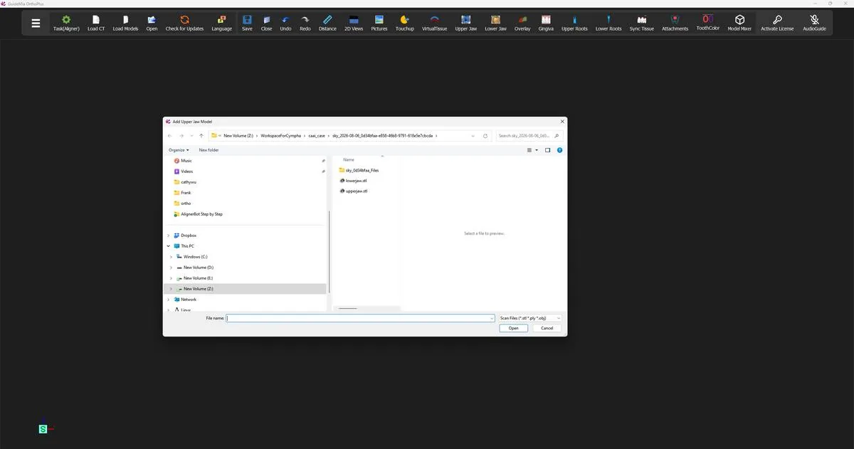 The file selection dialog, with the upper jaw scan chosen first.
 Both arches loaded and in occlusion, ready for the workflow to begin.
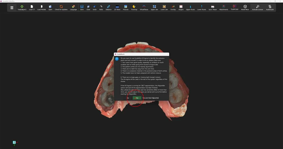
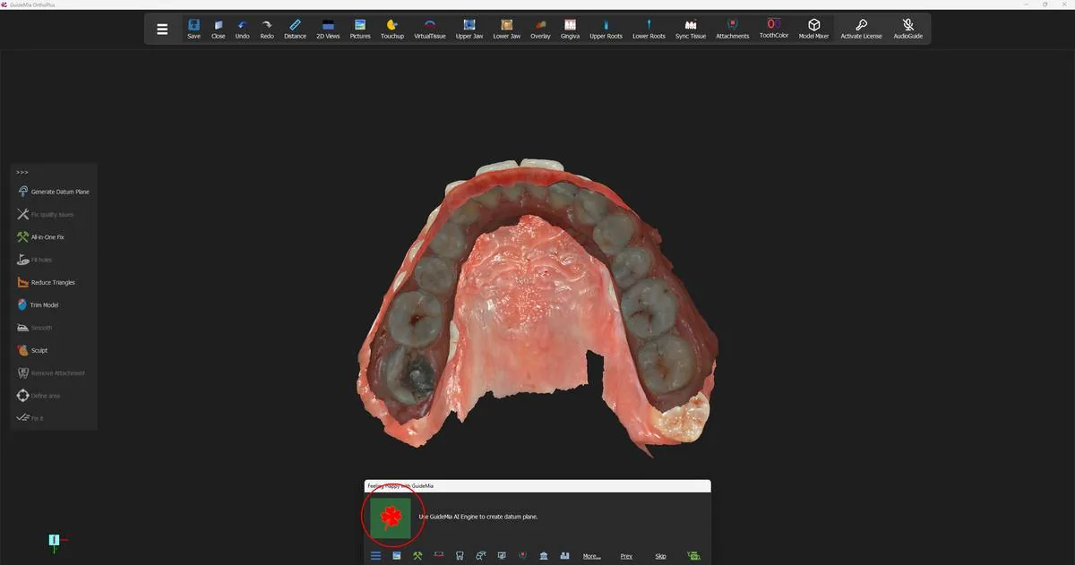 The upper jaw alone, with the Happy Button standing on the occlusion plane step.
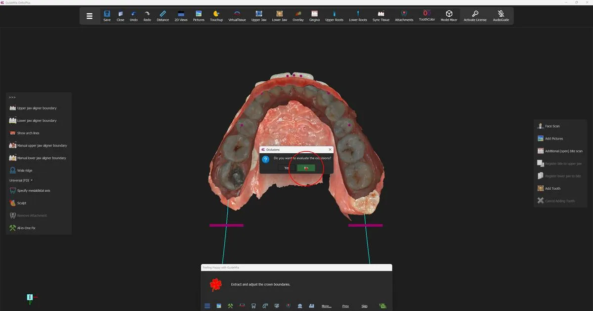 GuideMia offering to evaluate the occlusions before the plane is settled.
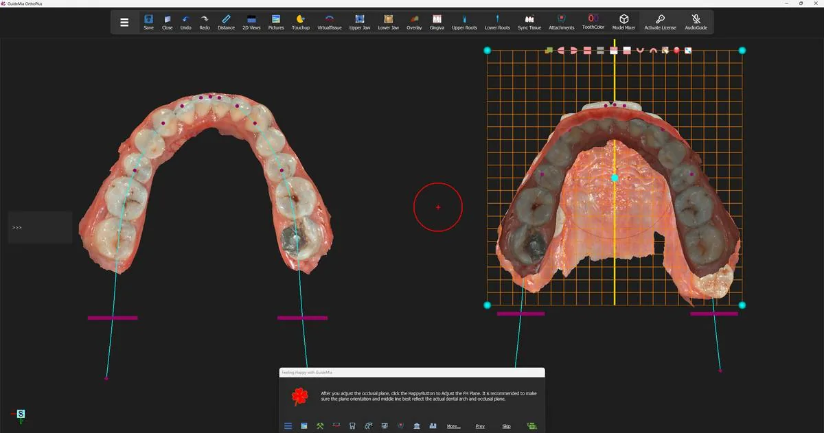 The proposed plane in the assembly window, with its centreline and corner handles, and the arch control points on the model at left.
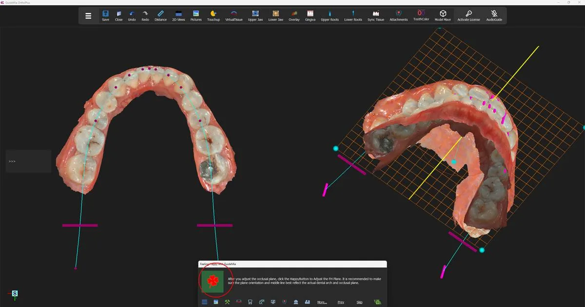 The same plane seen obliquely, where a cant that the occlusal view hides becomes visible.
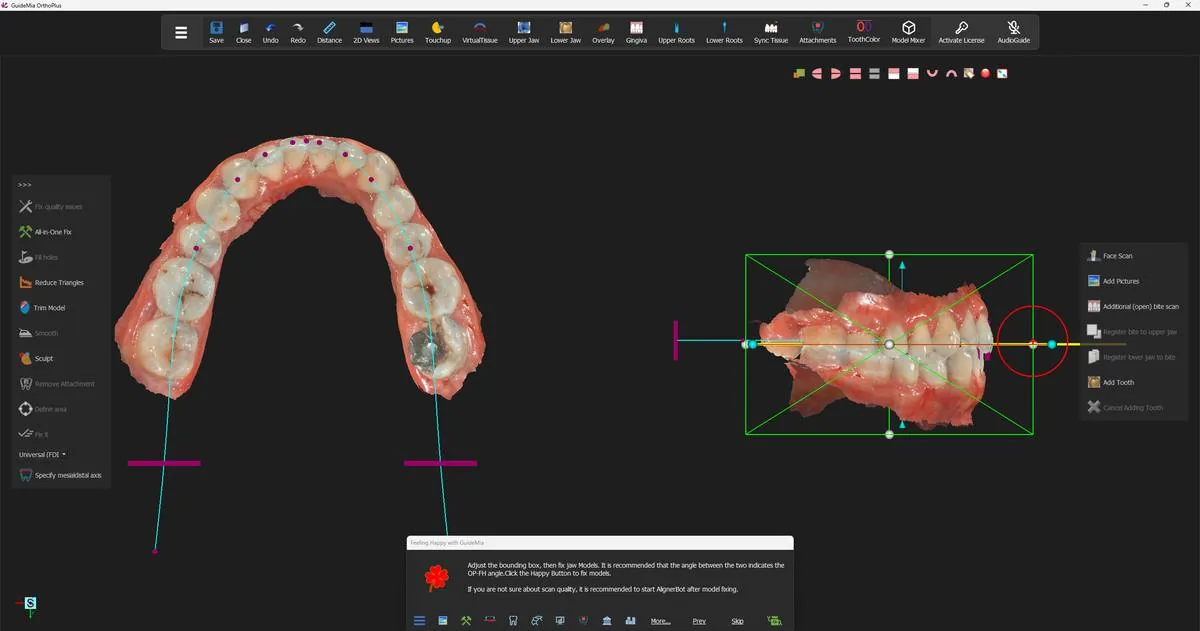 Pressing on has produced the bounding box, and the instruction has changed to the model-fixing step.
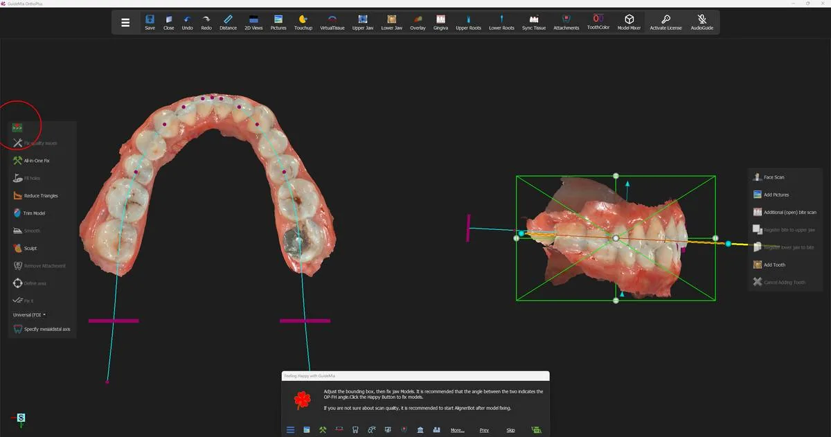 The ">>>" control at the head of the left-hand tool bar.
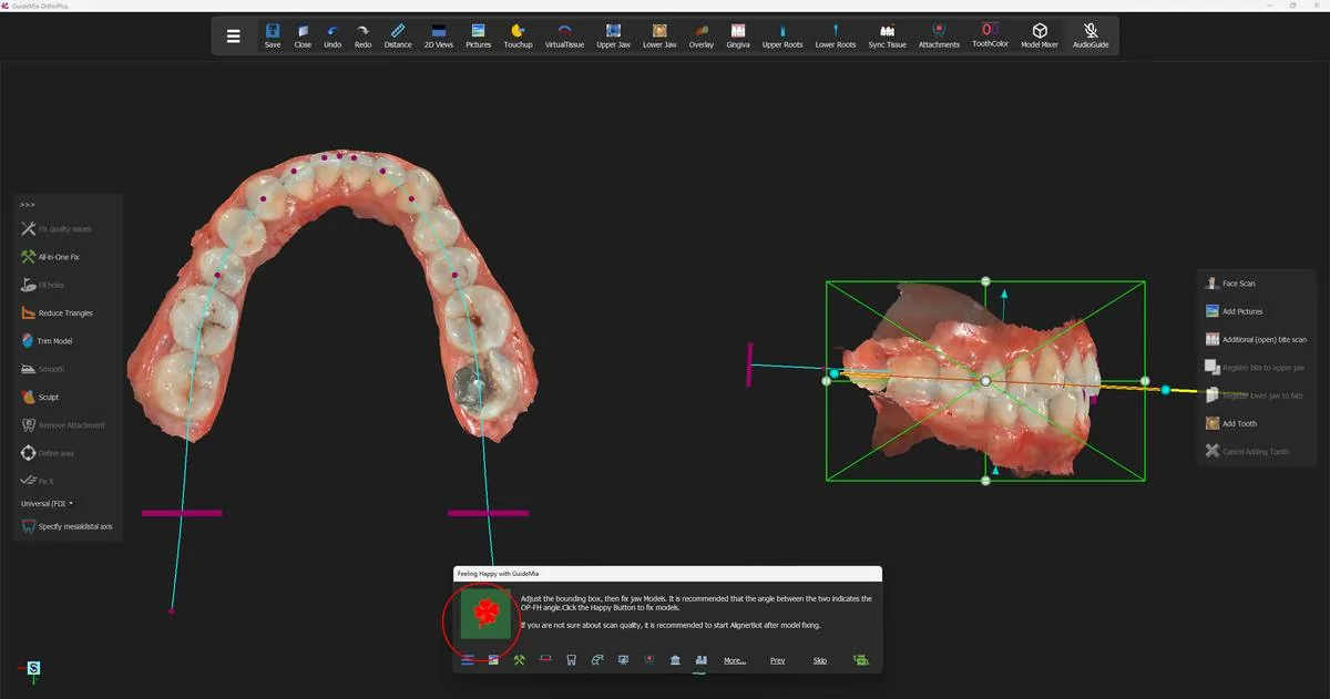 The bounding box on the models in the assembly window, with the occlusal plane still drawn through them.
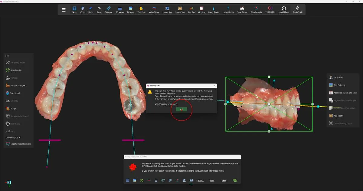 The scan-quality report, naming the teeth that need watching.
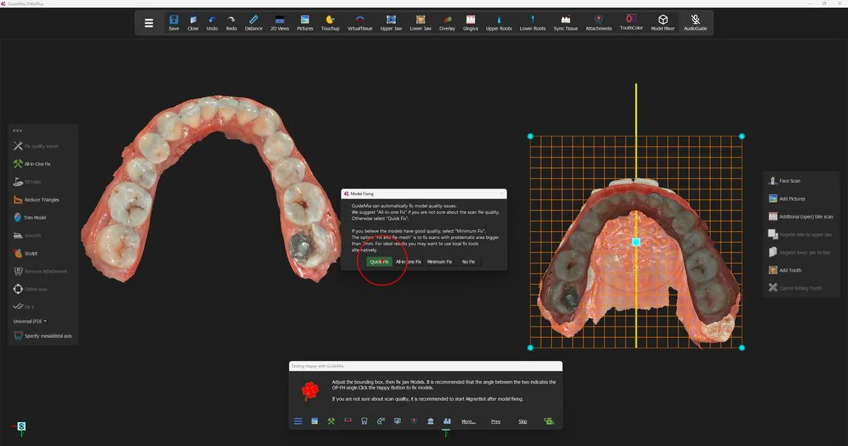 The repair options, with the models behind them.
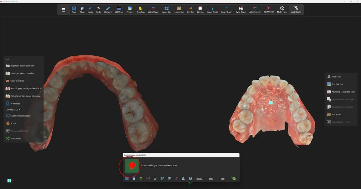 Both models repaired, with the Happy Button now offering crown boundaries.
 Both arches with the aligner boundary extracted — one continuous loop per jaw, following the gingival margin of every crown.
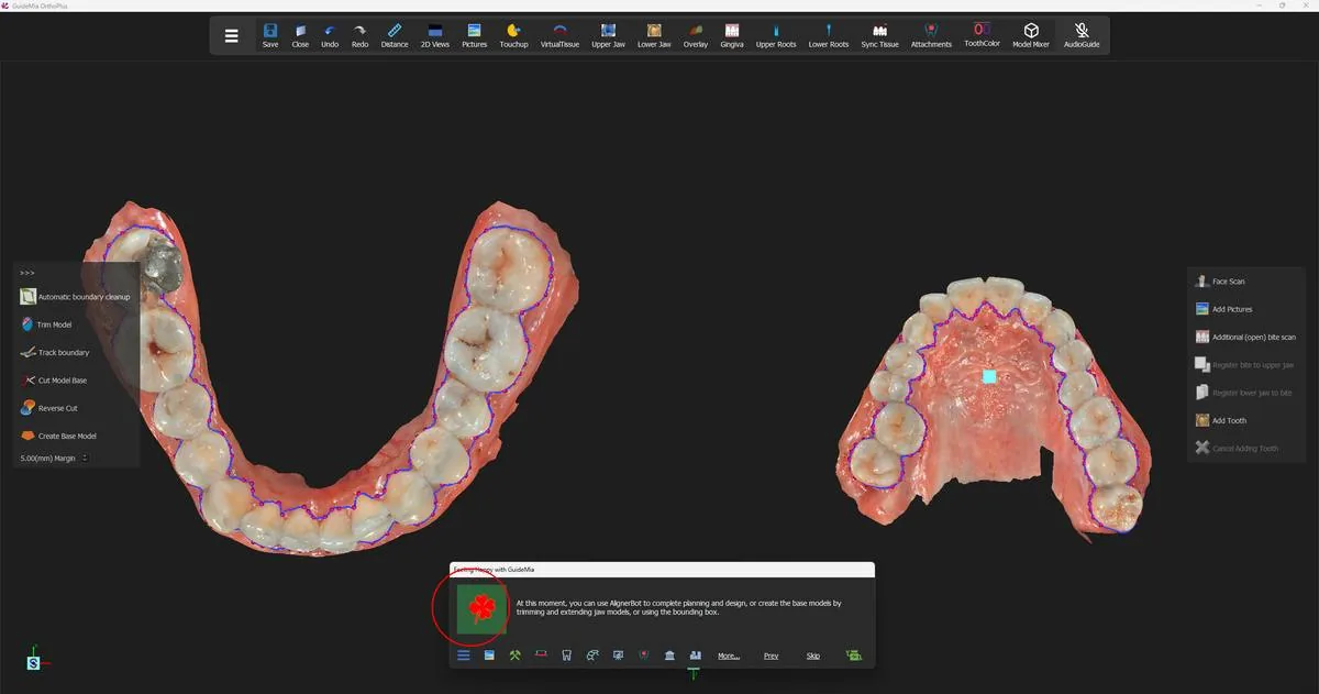 The first press of Create Base Model, with the trimming tools and the margin box on the bar at left.
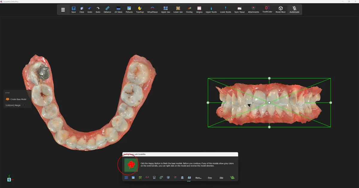 The second press, with the lower base model closed at left and both arches boxed in the assembly window at right.
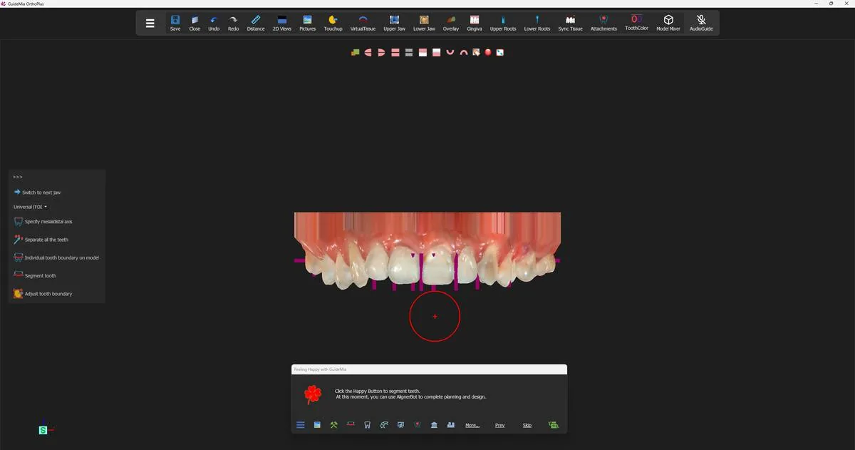 The finished base models, with the workflow now standing on tooth segmentation.
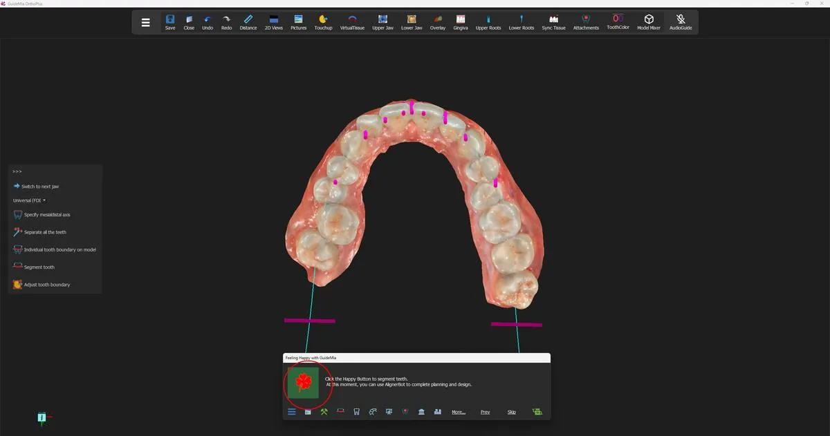 The upper arch from below, ready for mesial-distal axes; the short magenta bars are the axes already recognised.
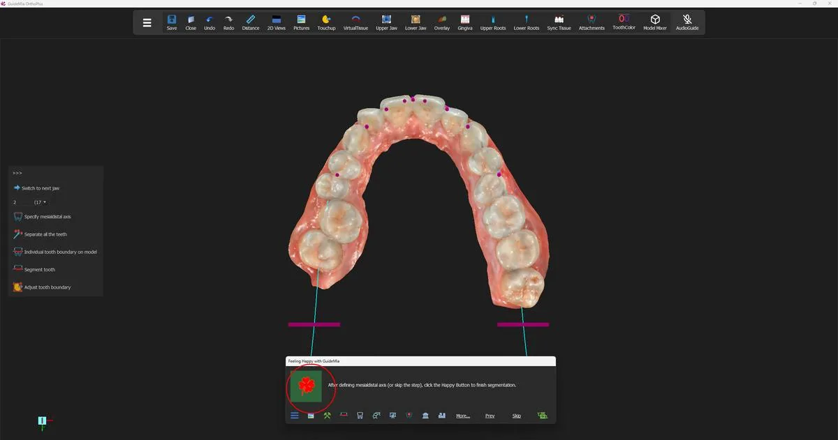 The tooth-number control preset to tooth 2 (FDI 17), with the segmentation about to run on the upper arch.
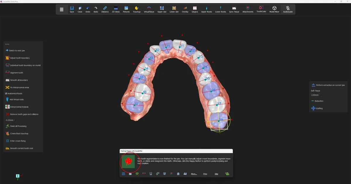 The upper arch separated: each crown its own object, numbered, in alternating colours, with its axes drawn on it.
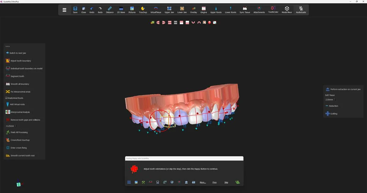 Middle-clicking the blue arrow on a tooth brings up its bounding box and rotation handle.
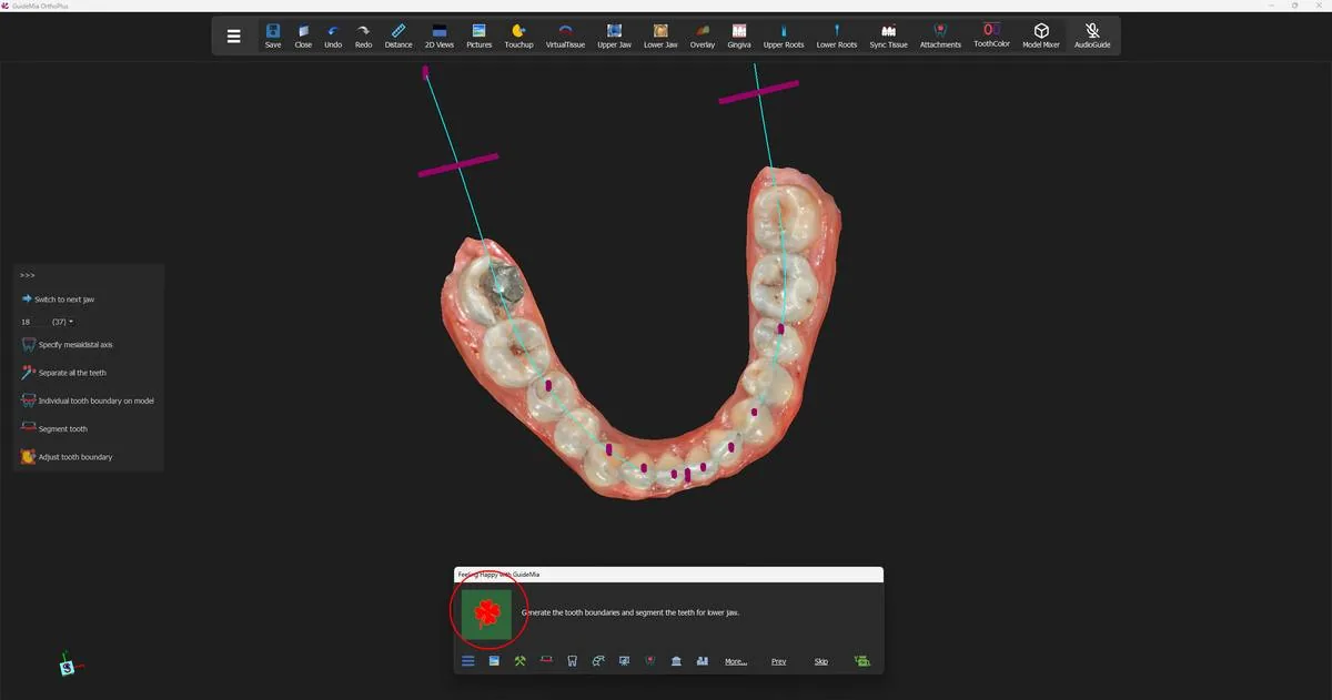 The lower arch, with the tooth-number control now at tooth 18 (FDI 37) and the arch curve and its range bars visible.
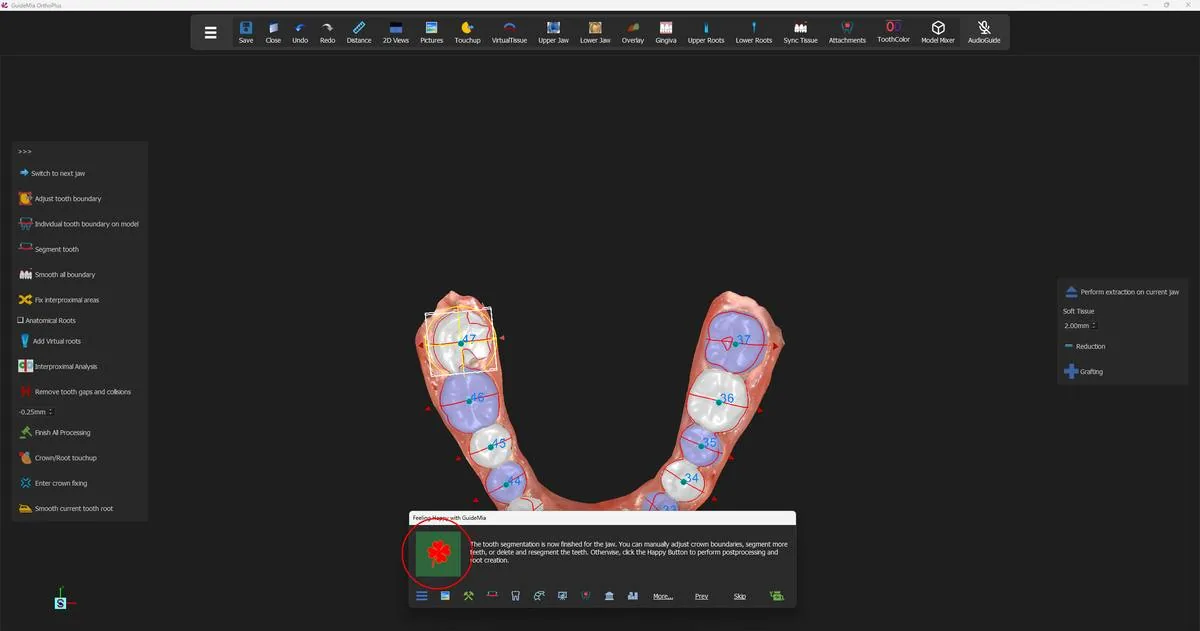 The lower arch segmented and numbered, ready for post-processing and roots.
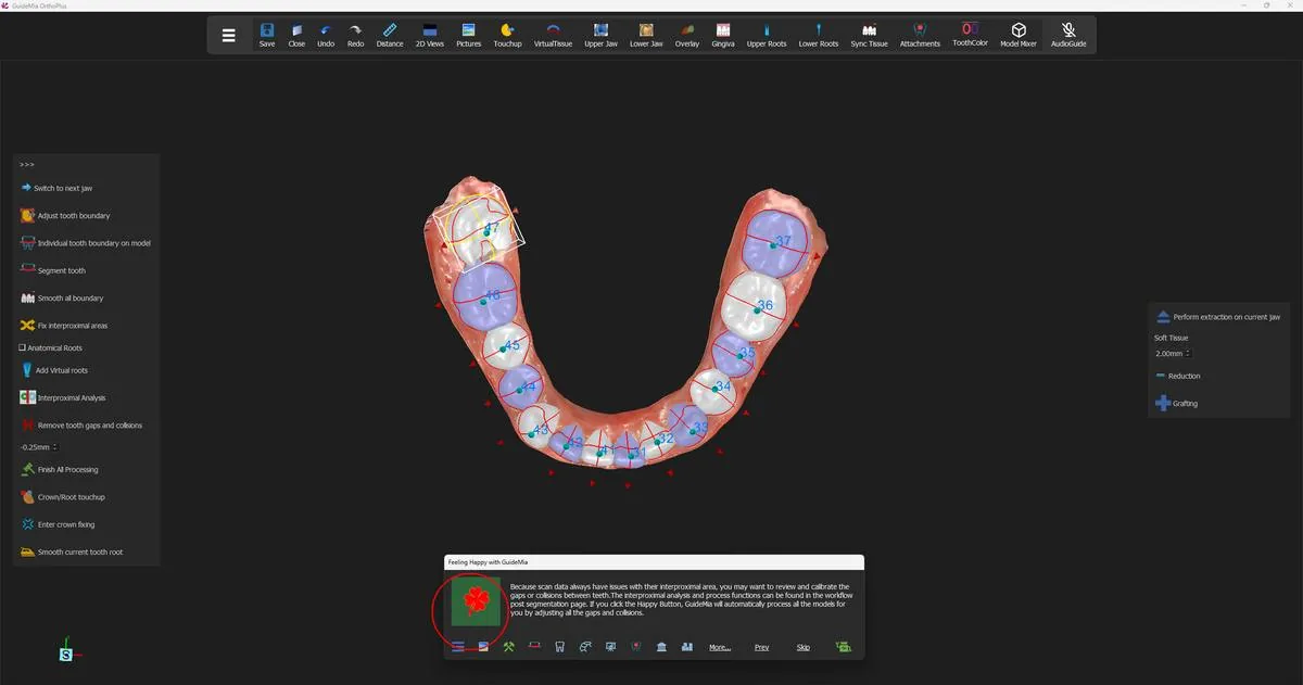 The calibration step, with both arches fully segmented, numbered and rooted.
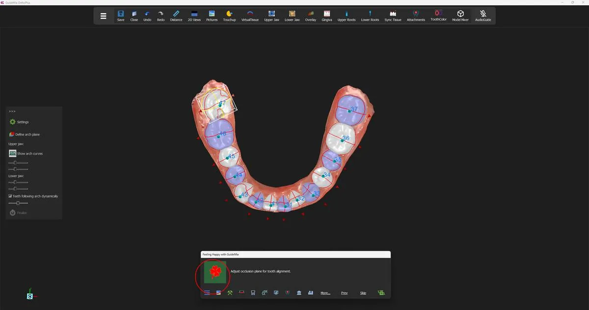 The teeth numbered and the occlusal plane brought up for a last look before alignment.
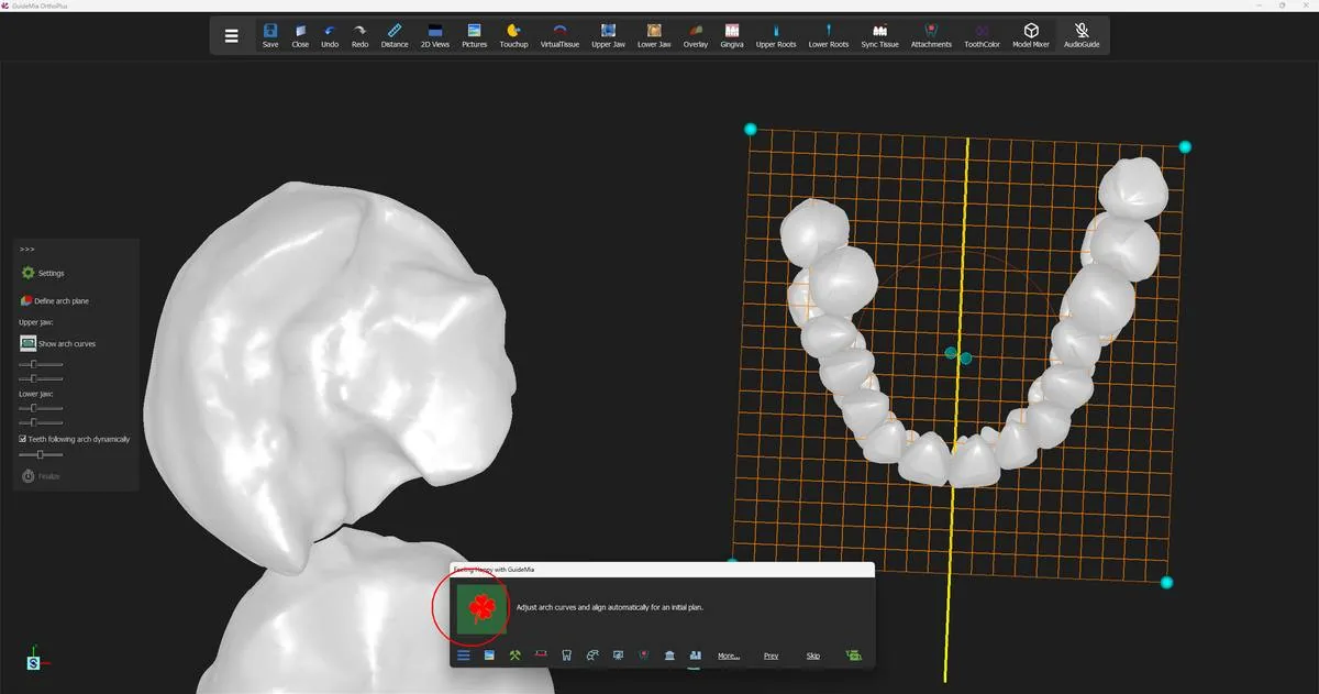 The arch curve on its grid, with the width and curvedness controls on the panel.
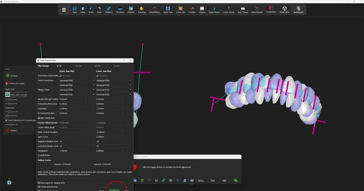 The Initial Treatment Plan dialog, with the real crowdedness value in the status bar at bottom left.
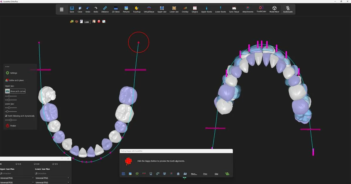 The proposed positions previewed against the arch curve, with the starting positions still visible behind them.
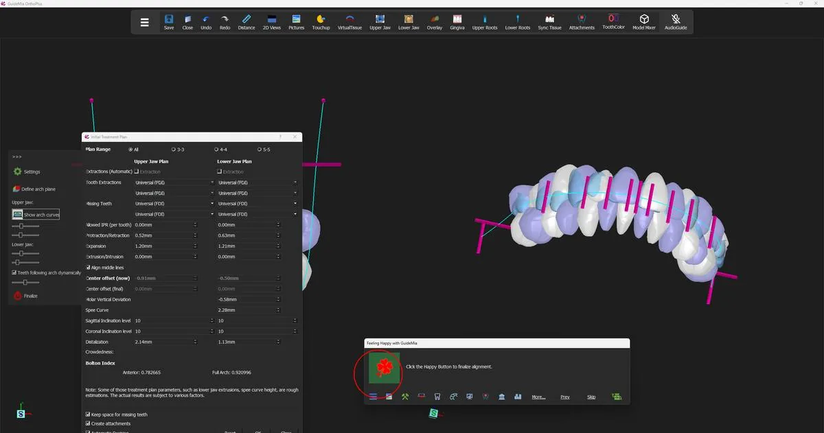 Finalising the alignment, with the treatment plan still open beside it.
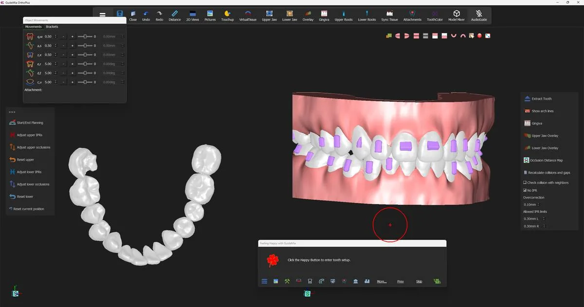 The finished alignment: both arches on their curves, attachments in place.
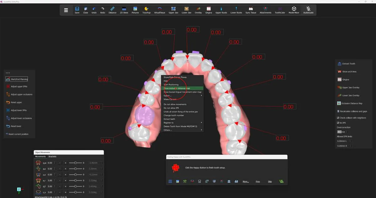 The right-click menu on a tooth, with the two map items above "Export ...".
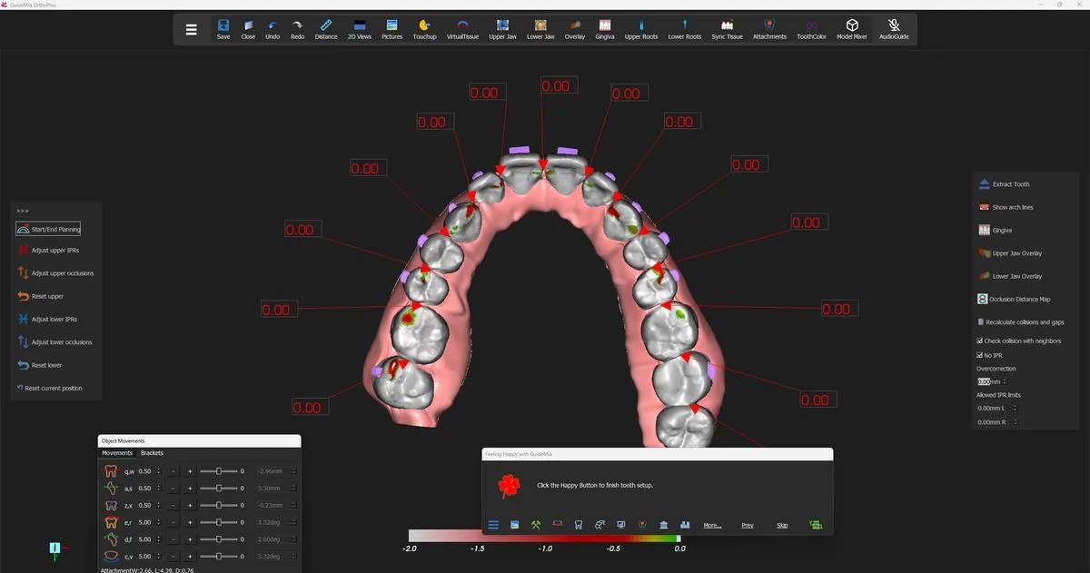 The occlusal distance map on the upper arch, with its −2.0 to 0.0 mm scale.
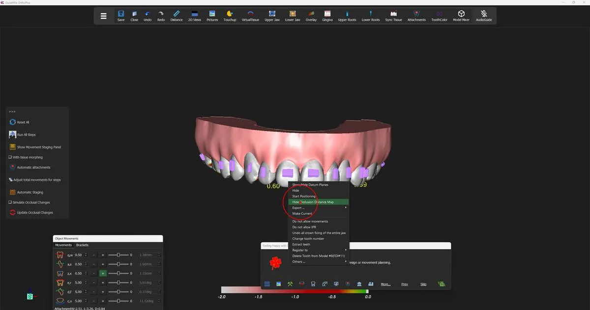 Turning the occlusal distance map off again from the same menu.
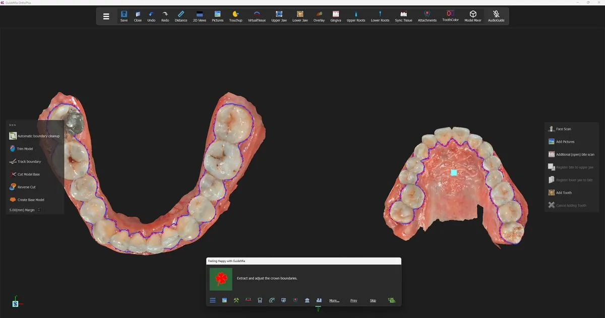 The same arches with no map on — the textured scans during crown boundary work.
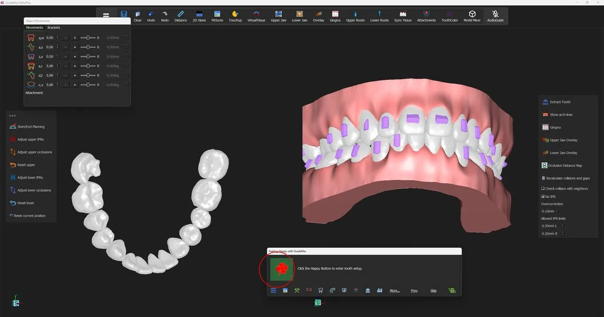 The case in tooth setup: the working object window on the left, the assembly on the right, and the manual tools on the panel.
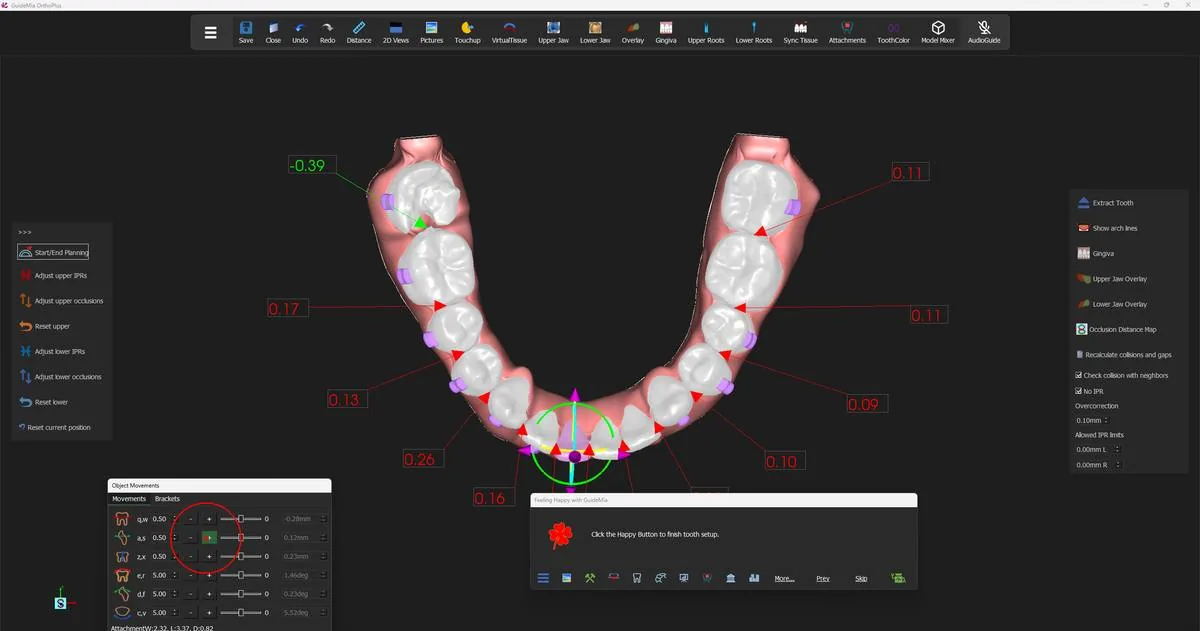 Moving a lower incisor by hand, with the interproximal collision and gap values live along the arch.
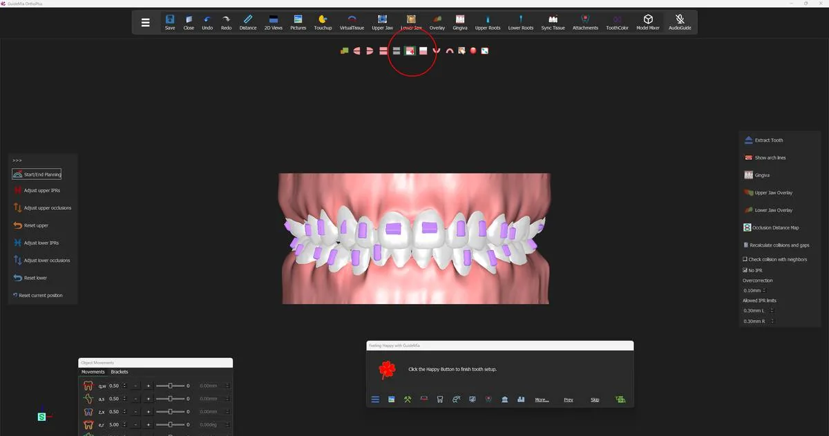 The upper and lower anteriors from the front, mid-setup.
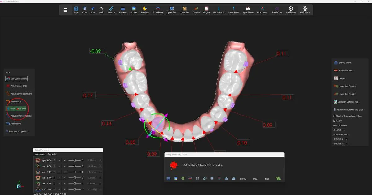 The lower arch after the first IPR pass: remaining collisions in red, a gap in green at the left molar.
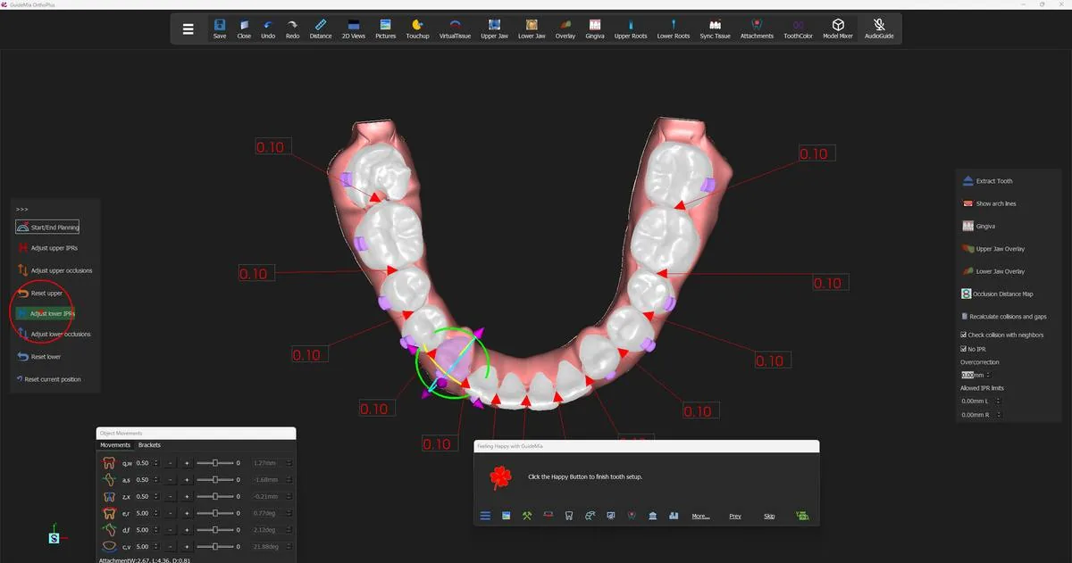 The same arch after re-running the IPR adjustment.
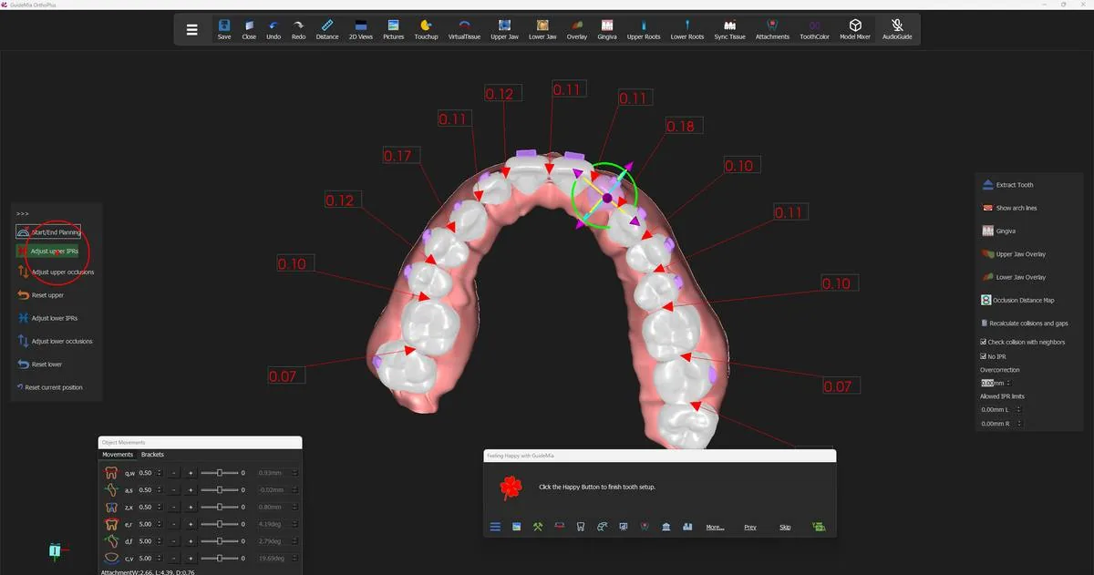 The upper arch after its own IPR pass.
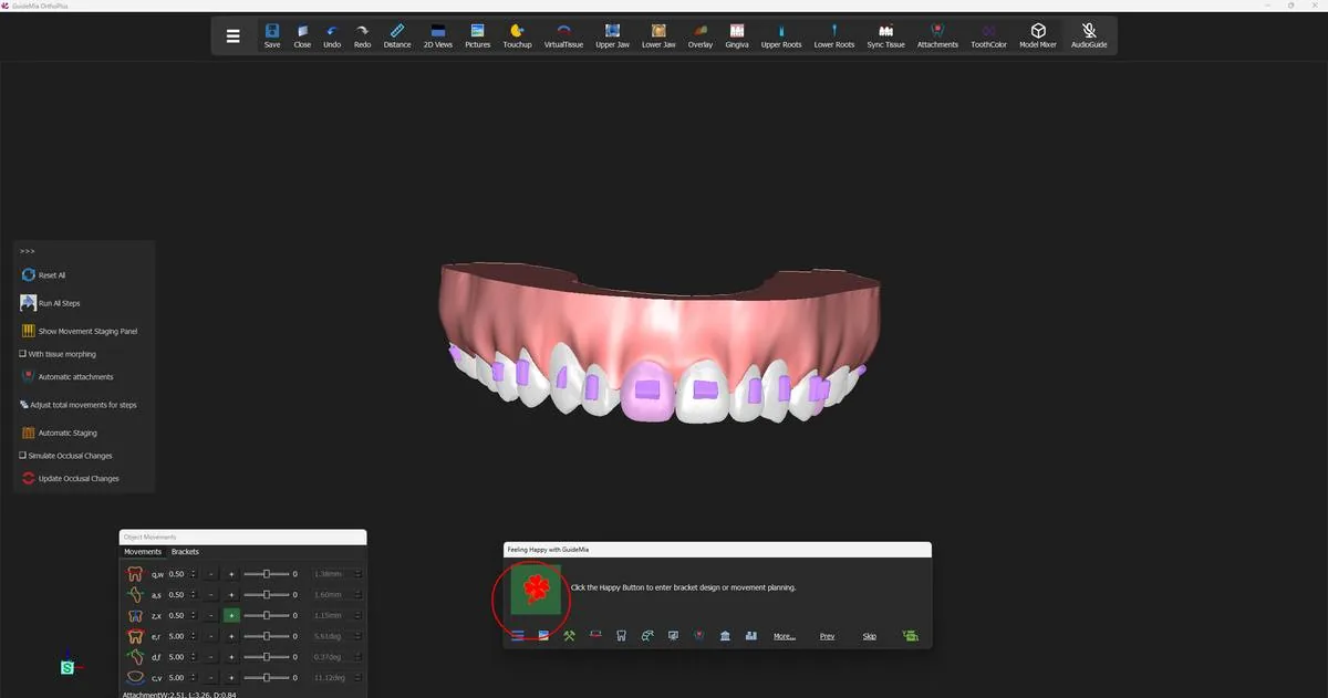 The Movement Planning page, with the staging and simulation tools on the panel.
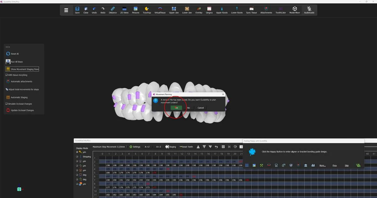 GuideMia confirming before it plans the movement orders.
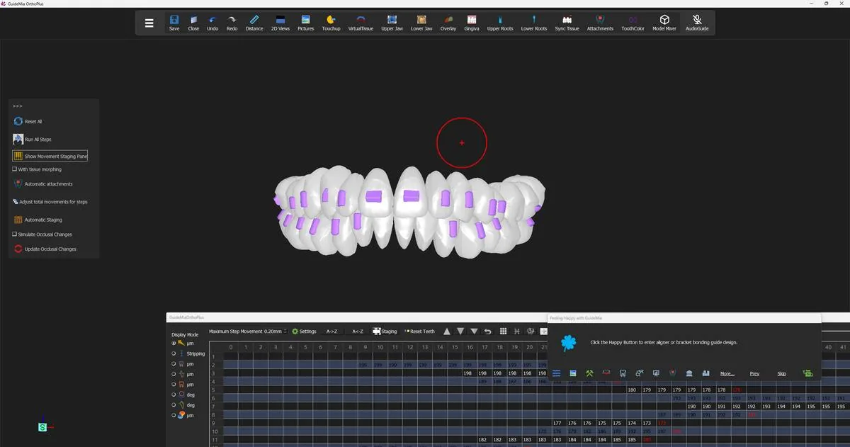 The plan playing back, with the model free to be turned while it runs.
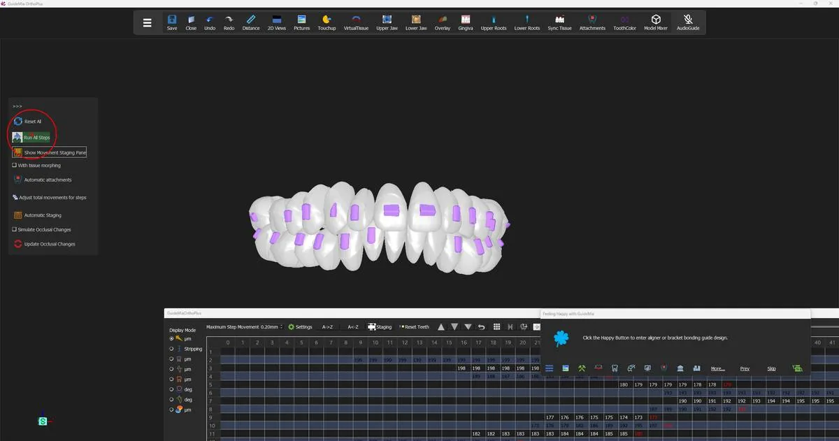 Running the simulation, with the staging toolbar and the movement table below.
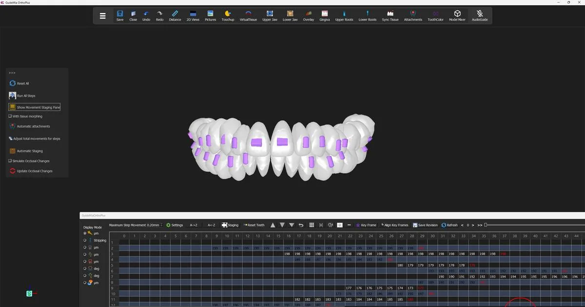 The movement table: rows are teeth, columns are steps, red text marks key frames.
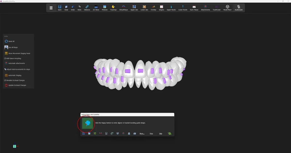 The teeth carrying their first set of attachments, with the Happy Button about to open aligner design.
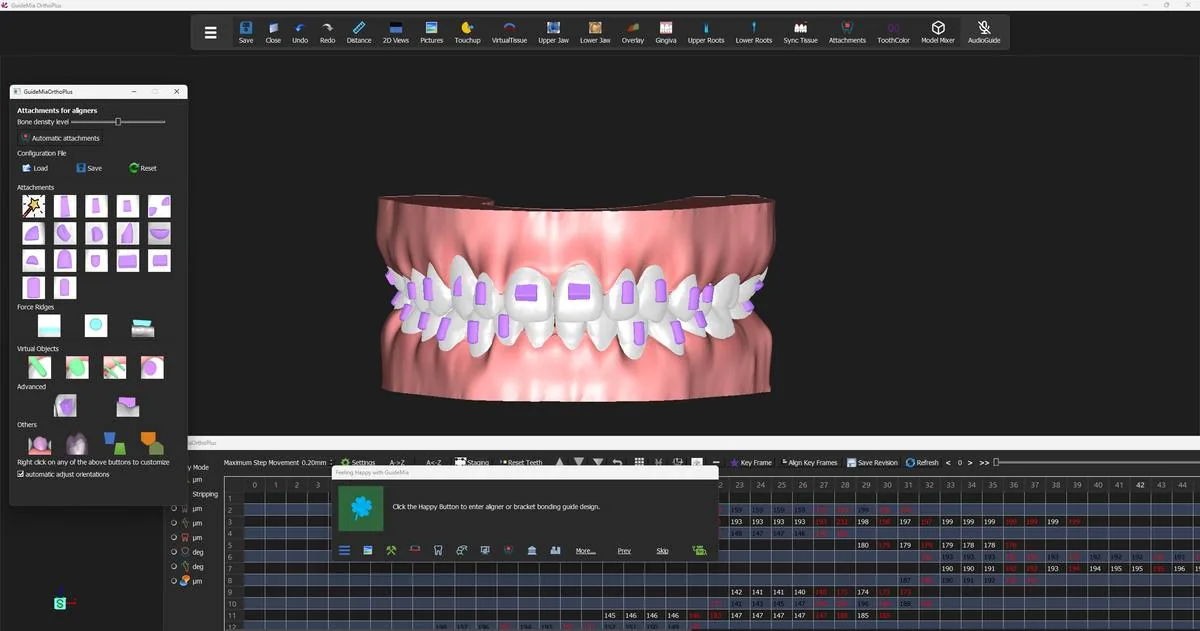 The attachment tools floated as their own window beside the model.
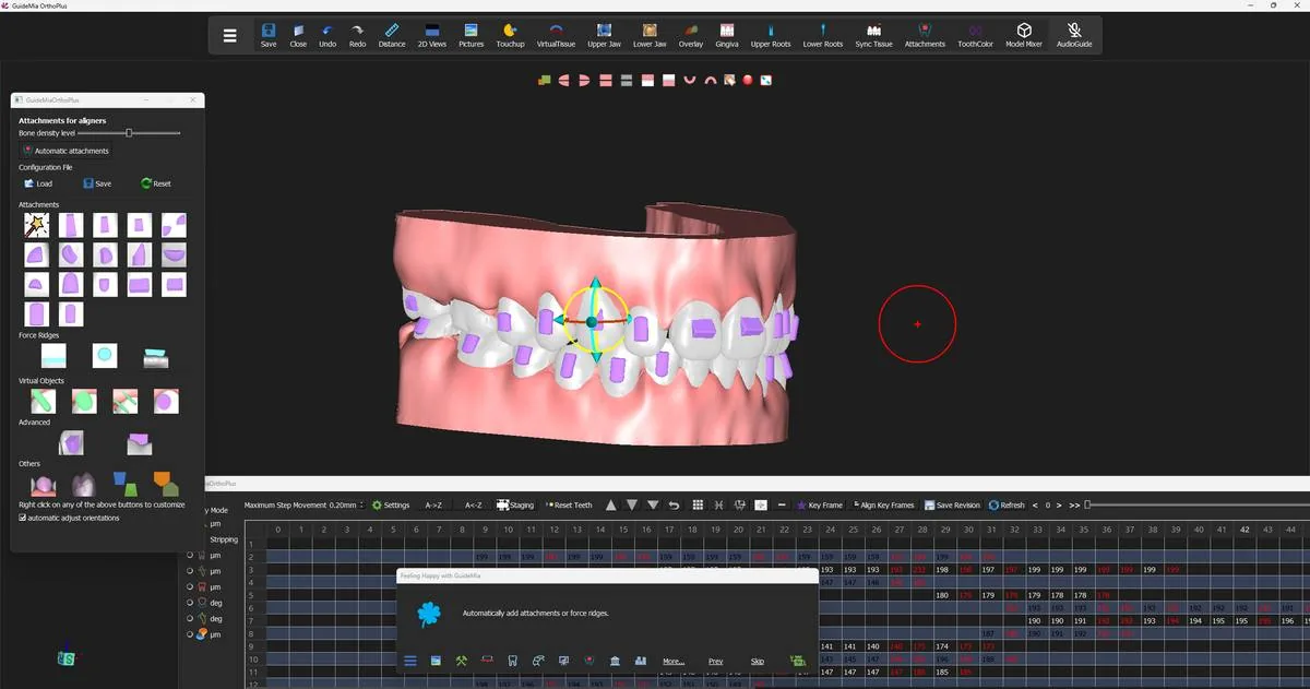 An attachment selected for adjustment, with its manipulator on the crown.
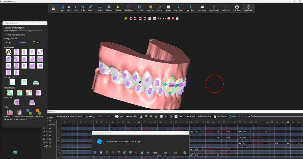 The same set checked from the side, with the model turned to bring the posterior teeth into view.
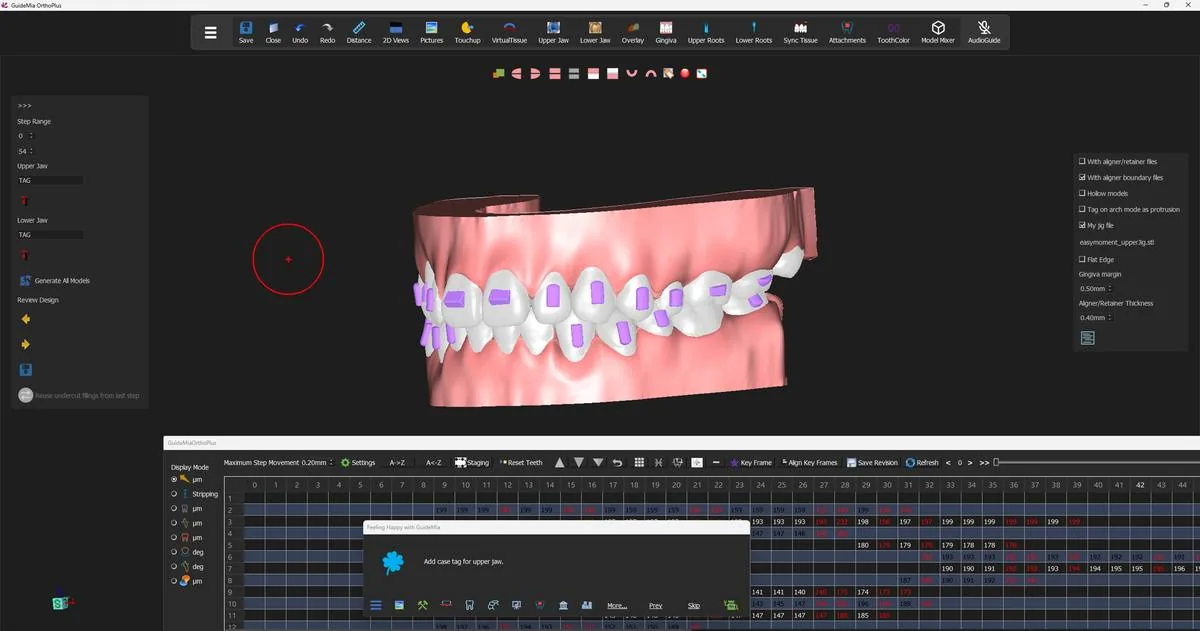 The Attachments step finished; the design sidebar and the option strip appear, ready for the case tag.
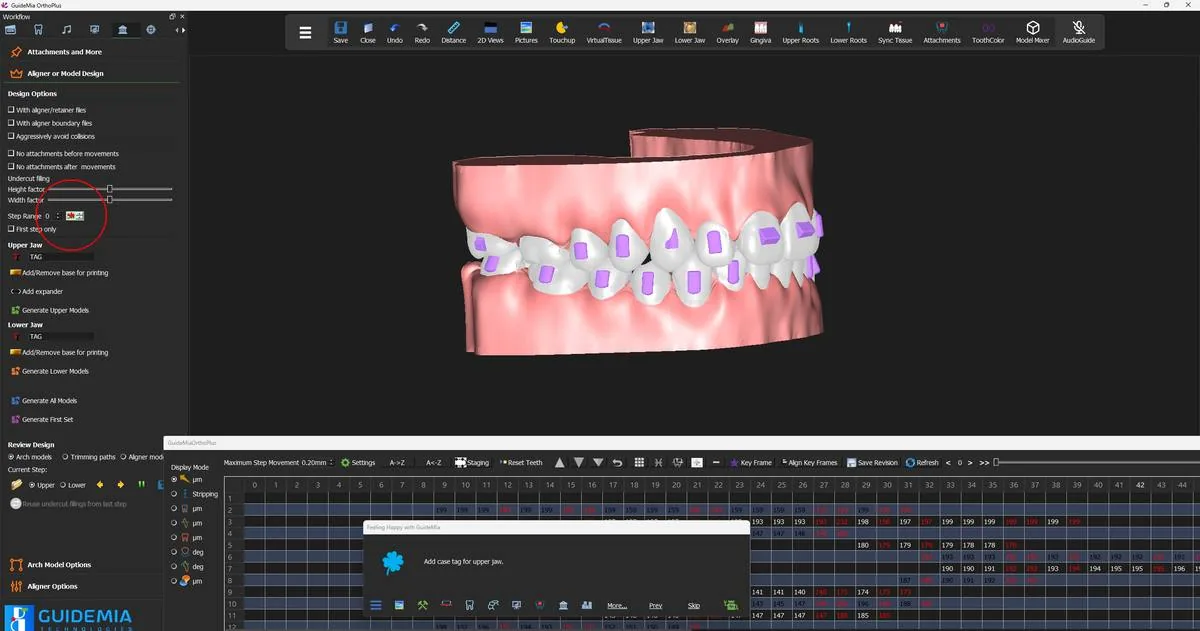 The full workflow panel, with the design options, step range and generate buttons on one page.
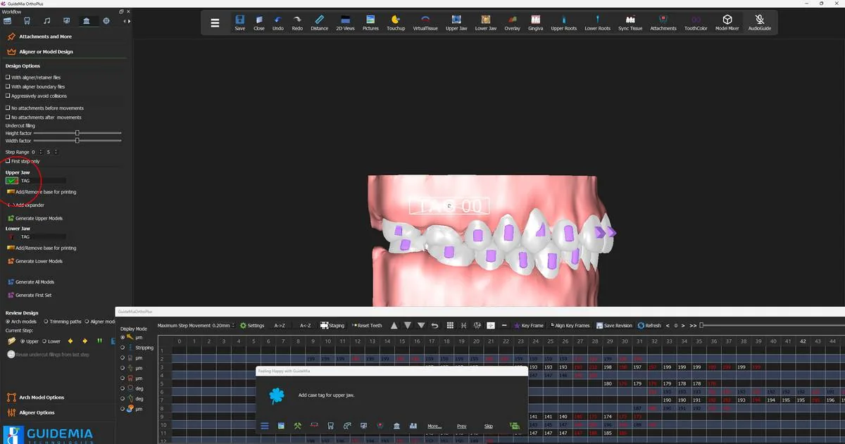 The upper case tag placed on the model, inside its manipulation frame.
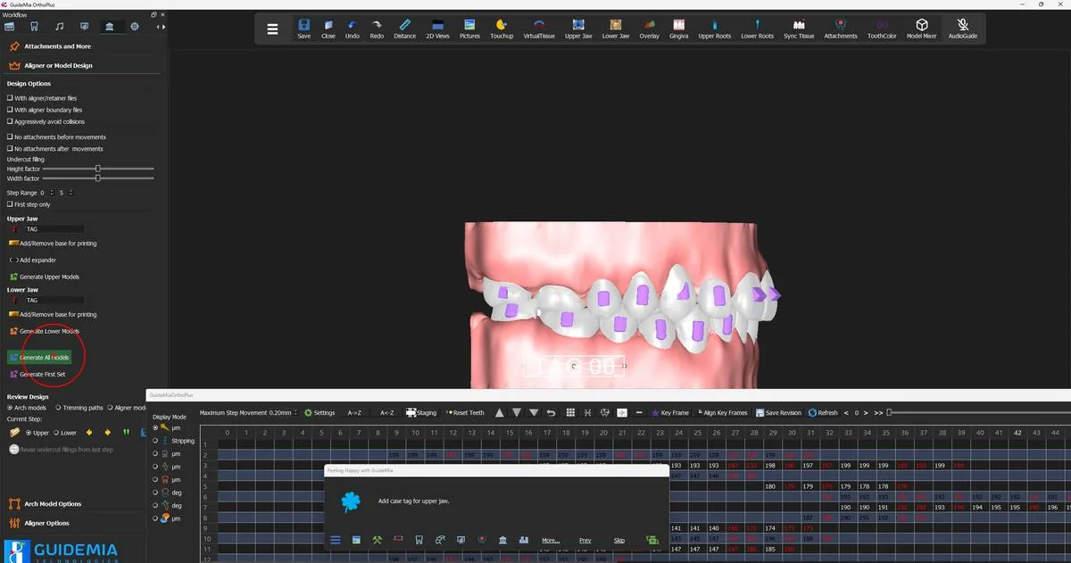 Generating every model in the step range for both jaws.
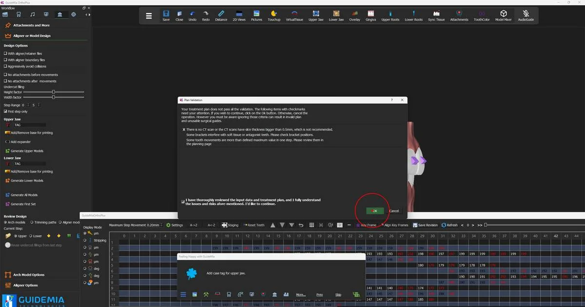 Plan Validation, with the acknowledgement that enables OK.
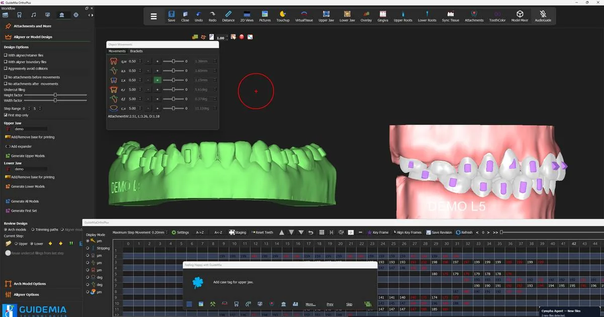 The first generated arch model, tagged and ready to inspect.
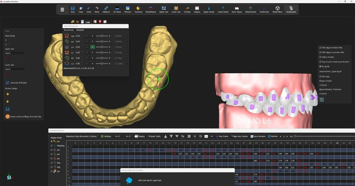 A generated lower arch model from the occlusal, with the interproximal fillings visible between the crowns.
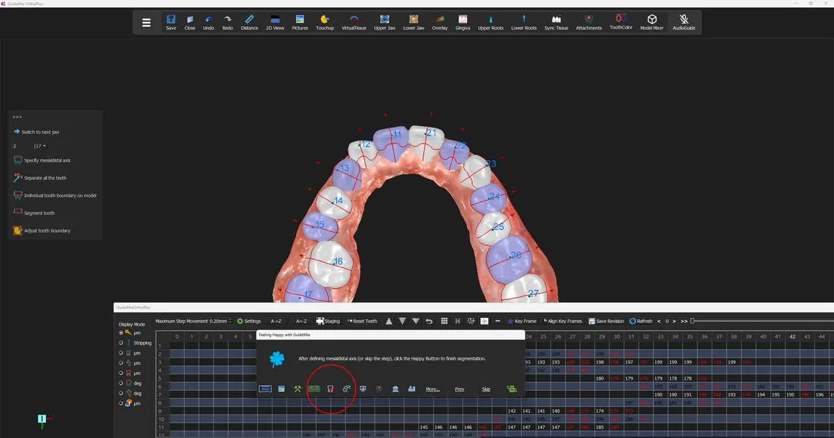 Stepping back to the segmentation page; the Happy Button follows to the step that belongs there.
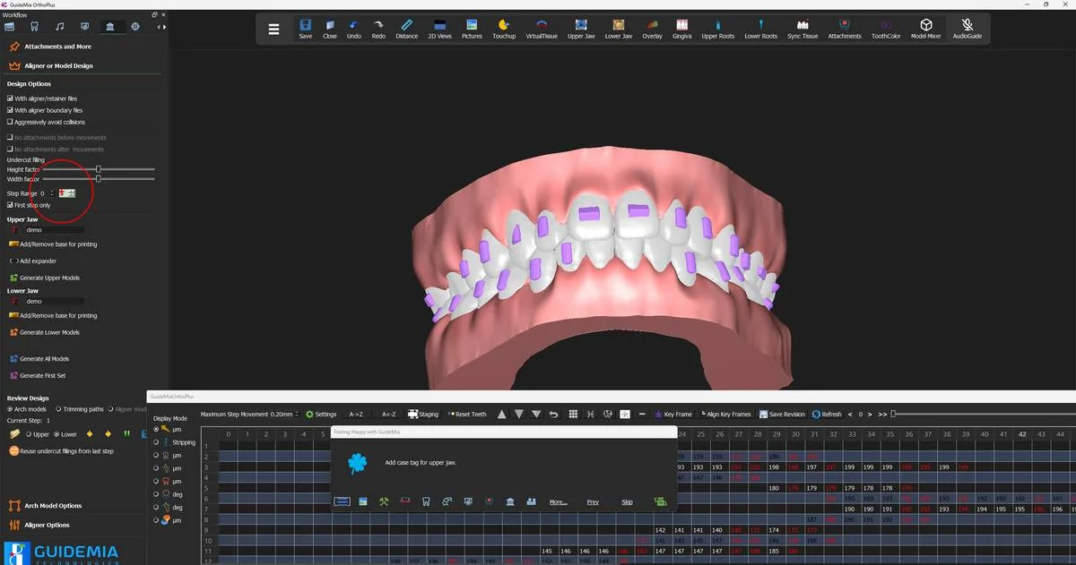 The design page in aligner mode: the aligner/retainer option ticked, the attachment-timing options greyed out.
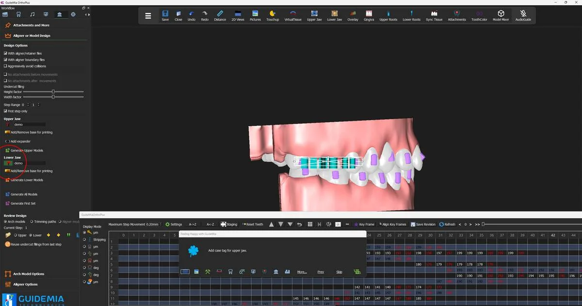 The case tag placed on the lower aligner, on the shell rather than on a base.
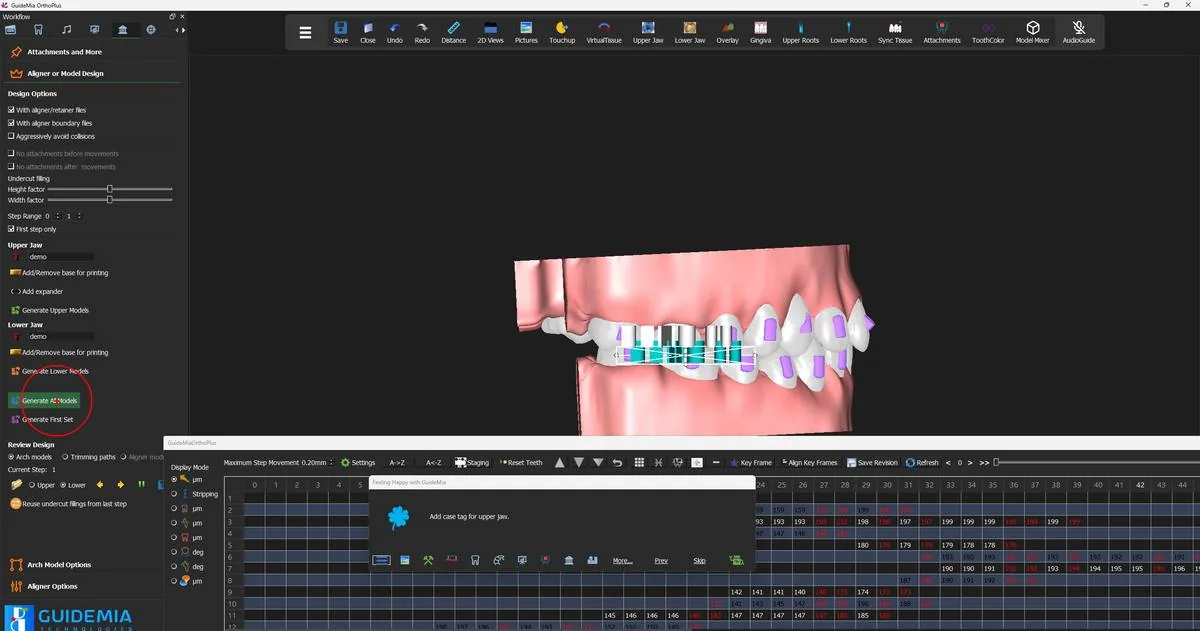 Generating the aligners for the step range.
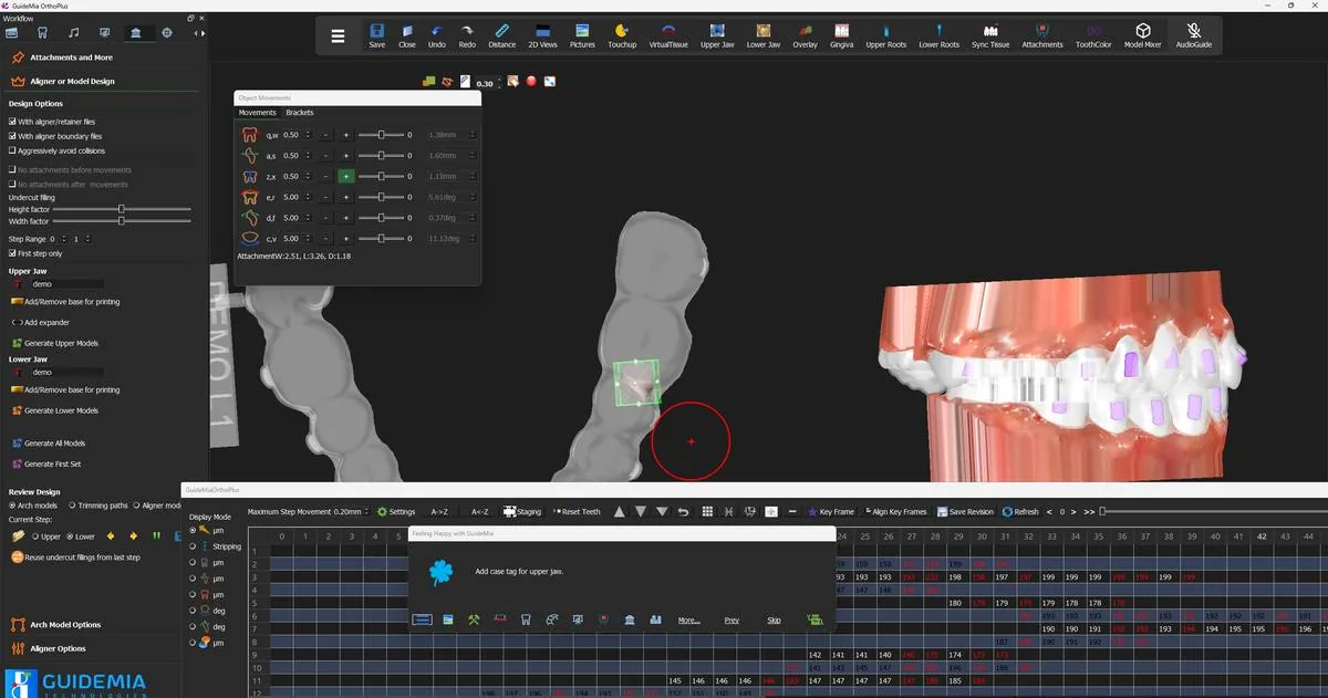 A generated aligner in the working window, with its case tag and an attachment socket selected.
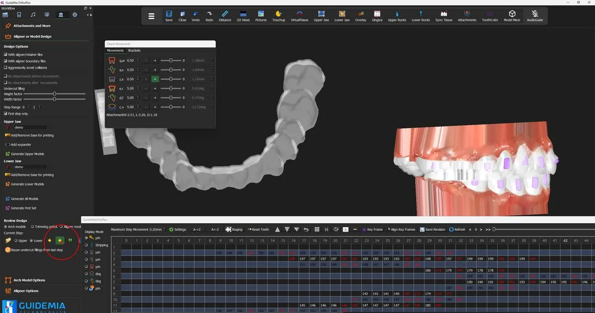 The same aligner from the occlusal, showing the margin all the way round the arch.
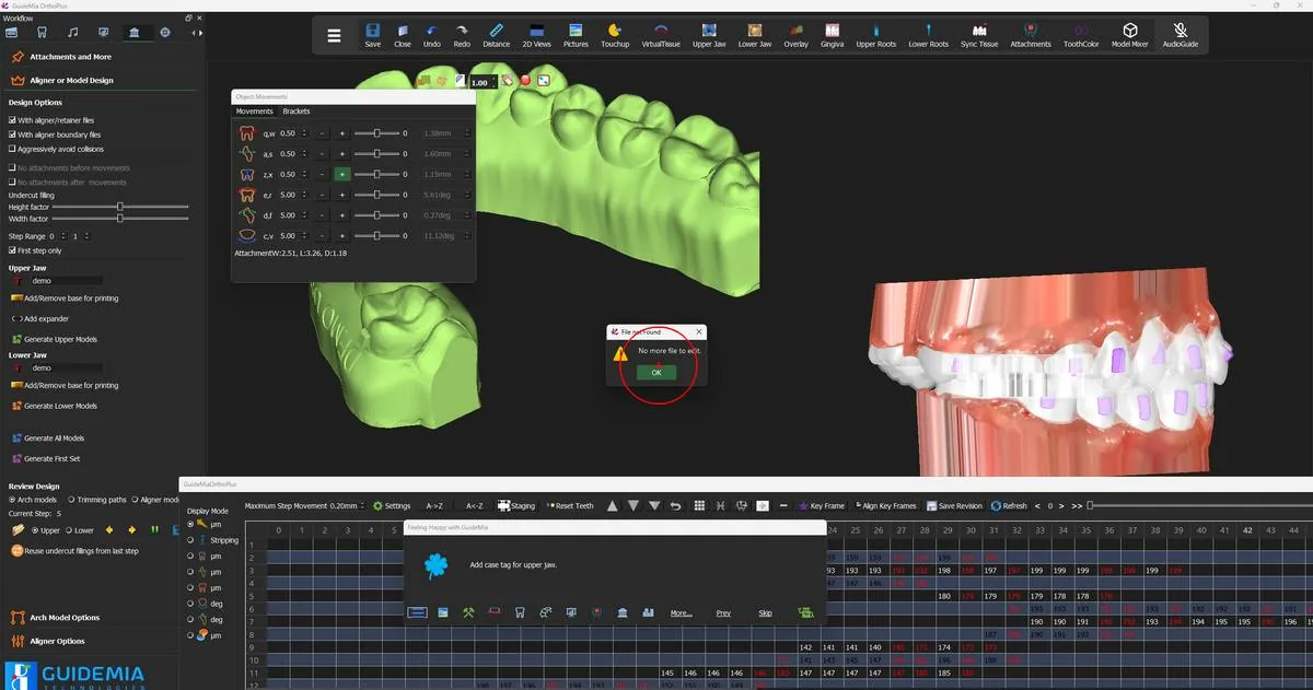 The end of the review set for one jaw.
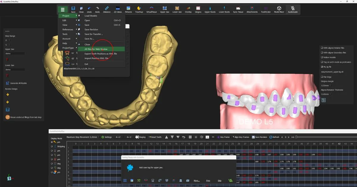 Packaging the case for online review from the Project menu.
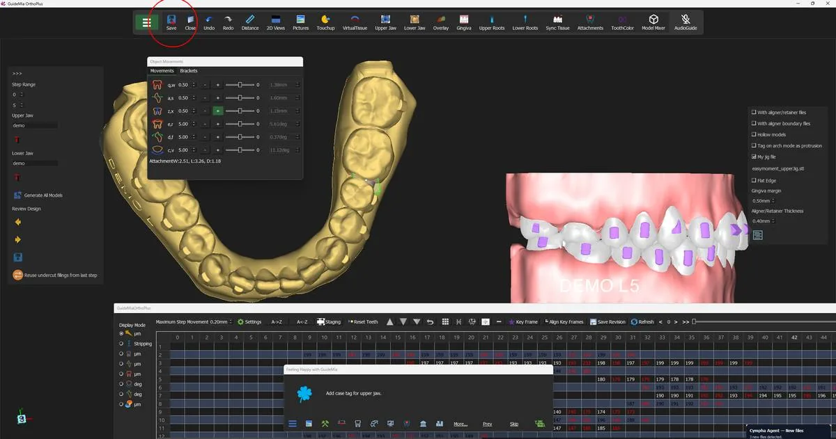 Saving the finished project.
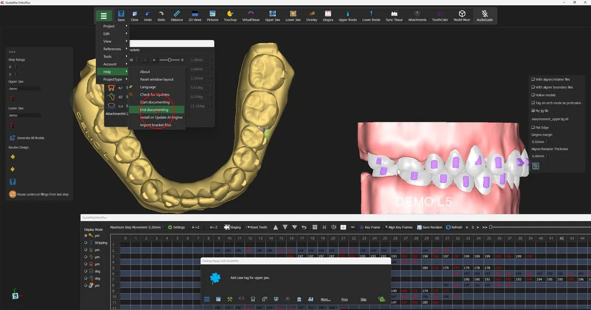 Ending the session record from the Help menu.